Acoustic reinforcing material block, application of acoustic reinforcing material block, micro loudspeaker and application of micro loudspeaker

A micro-speaker and reinforcement material technology, applied in the field of speakers, can solve the problems of limited product ID design, increased mold cost, loss of natural feeling, etc., to achieve improved drop resistance reliability, reduced fragmentation, and excellent mechanical properties Effect

Pending Publication Date: 2022-07-29
SSI NEW MATERIAL (ZHENJIANG) CO LTD
View PDF1 Cites 3 Cited by
  • Summary
  • Abstract
  • Description
  • Claims
  • Application Information

AI Technical Summary

Problems solved by technology

[0005] 1. Simply improve the structural size of the front acoustic cavity and sound outlet, but it is easily limited by the fixed ID design of the product;
[0006] 2. Apply the corresponding audio algorithm to correct the high frequency, but it is easy to cause the sound effect to be "distorted" and lose the sense of nature;
[0007] 3. Adding a front cavity resonator, or adding a filter structure in the front cavity resonator will increase the cost of the mold, and at the same time, it will also be limited by the design of the product ID

Method used


Image

  • Acoustic reinforcing material block, application of acoustic reinforcing material block, micro loudspeaker and application of micro loudspeaker
  • Acoustic reinforcing material block, application of acoustic reinforcing material block, micro loudspeaker and application of micro loudspeaker
  • Acoustic reinforcing material block, application of acoustic reinforcing material block, micro loudspeaker and application of micro loudspeaker

Examples


Embodiment 1

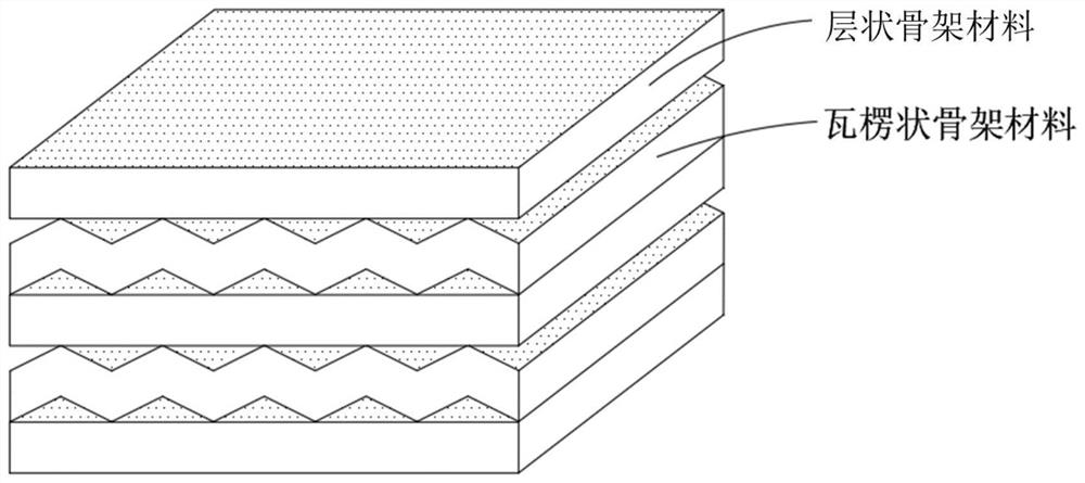
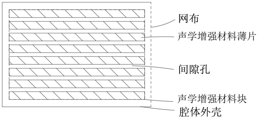
[0062] This embodiment provides an acoustic enhancement material block, based on the total weight of the acoustic enhancement material block as 100%, the material includes 6.4% polyacrylate suspension, 0.1% CMC, 12.6% skeleton material, and the balance is porous material . Wherein, the porous material used is MFI structural molecular sieve, and its Si / M mass ratio is 350, wherein M is aluminum; the skeleton material used is formed by alternately stacking layered fiber paper, and the fiber paper is made of chopped alkali-free glass fibers passing through It is obtained by wet process, and it is surface-treated with silane coupling agent KH550. The gram weight per unit area of ​​the fiber paper is 25g / m2 2 , the fiber diameter is 7 μm.

[0063] In the process of preparing the above-mentioned acoustic reinforcing material block, the fiber paper is first cut into a size and shape suitable for the speaker cavity to be filled, and then the polyacrylate suspension, CMC and MFI mole...

Embodiment 2

[0066] This embodiment provides a miniature speaker, Figure 3-Figure 4 It is a schematic diagram of the structure of the micro-speaker. like Figure 3-Figure 4 As shown, the micro-speaker includes an upper shell 1 , a lower shell 2 and a speaker unit 4 .

[0067] The upper shell 1 and the lower shell 2 are glued together to form a sealed inner cavity. In appearance, the upper shell 1 and the lower shell 2 together form a rectangular shell of the micro-speaker.

[0068] Wherein, the lower shell 2 is the bottom shell of the micro-speaker.

[0069] The upper shell 1 is the top shell and the side shell of the micro speaker, and the top and the side surface of the upper shell 1 are integrally formed. One side surface of the upper shell 1 is provided with a sound outlet 7 . The inner top surface of the upper shell 1 is provided with three vertically downward limiting protrusions 61, the limiting protrusions 61 are located on the opposite side and the adjacent side of the sound...

Embodiment 3

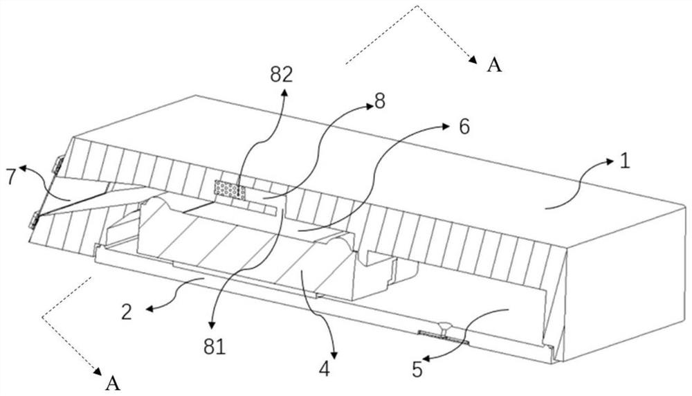
[0075] This embodiment provides a miniature speaker, Figure 5-Figure 8 It is a schematic diagram of the structure of the micro-speaker. like Figure 5-Figure 8 As shown, the micro-speaker includes an upper shell 1 , a lower shell 2 and a speaker unit 4 .

[0076] like Image 6 As shown, the upper shell 1 and the lower shell 2 are bonded to form a sealed inner cavity. In terms of appearance, the upper shell 1 and the lower shell 2 together form a rectangular shell of the micro speaker. The upper shell 1 is the top shell, the side shell and the inner shell of the micro-speaker, and the lower shell 2 is the bottom shell of the micro-speaker.

[0077] The upper casing 1 of this embodiment is further provided with a first blocking wall 91 , a second blocking wall 92 and an annular boss 93 on the basis of the upper casing 1 in the second embodiment. Specifically, the upper casing 1 of this embodiment includes a first casing 11 and a second casing 31 . The first shell 11 is the...


PUM

PropertyMeasurementUnit
diameteraaaaaaaaaa
diameteraaaaaaaaaa

Abstract

The invention provides an acoustic reinforcing material block and an application thereof, and a micro loudspeaker and an application thereof. A structural framework of the acoustic reinforcing material block is formed by a single-layer framework material or formed by alternately laminating more than two layers of framework materials, and the raw materials of the acoustic reinforcing material block further comprise a porous material, an adhesive and an assistant which are loaded in the structural framework. The invention further provides a miniature loudspeaker, the miniature loudspeaker comprises an upper shell, a lower shell and a loudspeaker unit, the upper shell and the lower shell form an inner cavity, the loudspeaker unit is located in the inner cavity, a sound outlet hole is formed in one side of the upper shell, and the inner cavity is divided into a front cavity and a rear cavity by taking a vertical plane where the side face, opposite to the sound outlet hole, of the loudspeaker unit as a boundary; the front cavity is communicated with the sound outlet hole; the front cavity is provided with a sound outlet hole; a front cavity resonant cavity communicated with the front cavity is arranged in the upper shell, and the front cavity resonant cavity is filled with acoustic reinforcing materials. The miniature loudspeaker can effectively improve the flatness of the high-frequency performance curve of the loudspeaker.

Description

technical field [0001] The present invention relates to the technical field of loudspeakers, in particular to an acoustic enhancement material block and its application, a miniature loudspeaker and its application. Background technique [0002] With the continuous development of mobile terminal equipment, users have higher and higher requirements for mobile phone audio quality. In addition to overall loudness, users' requirements for sound quality are also gradually improving. The high-frequency performance of micro-speakers, its frequency band width, and unevenness seriously affect the user's experience of music taste and details. [0003] Due to the existence of the front acoustic cavity resonance and the unit dome resonance, the high frequency frequency response FR curve of the loudspeaker is often not flat and the frequency band width. In order to solve this problem, the method of adding a front cavity resonator is mostly adopted. However, in this way, the peak value (...

Claims


Application Information

Patent Timeline
Patent Type & Authority Applications(China)
IPC IPC(8): B32B3/08B32B3/24B32B3/28B32B17/02B32B17/12B32B29/08H04R19/02H04R31/00
CPCB32B3/266B32B3/28B32B29/08B32B5/08B32B5/16B32B5/30B32B5/26B32B3/08H04R19/02H04R31/00B32B2250/42B32B2262/101B32B2264/10B32B2264/108B32B2457/00
Inventor 张磊郭明波龚畅赵峻杰马院红刘仁坤
Owner SSI NEW MATERIAL (ZHENJIANG) CO LTD
Why Eureka
Try Eureka