High-power compact electro-hydraulic wind generating set assembly

A wind turbine, compact technology, applied in the direction of wind motor combination, wind engine, engine, etc., can solve the problems of mechanical friction loss, difficulty in ensuring accuracy, and reduction of maintenance workload, so as to reduce the weight of the nacelle, achieve low price and network, installation cost reduction effect

Pending Publication Date: 2022-07-29
钟彪
View PDF0 Cites 0 Cited by
  • Summary
  • Abstract
  • Description
  • Claims
  • Application Information

AI Technical Summary

Problems solved by technology

like figure 1 As shown, it is an assembly diagram of a traditional box-type wind turbine. The gearbox-type wind turbine includes a speed-up gearbox 1, a coupling 3, and a generator 2. One end of the speed-up gearbox 1 is connected to the impeller, and the other end is connected through the coupling The shaft is connected to the generator 2. This structure has the following characteristics: (1) The speed-up gearbox 1 is one of the most critical components of the wind turbine. At present, the speed-up gearbox is difficult to process, expensive, and has a high failure rate , prone to problems such as failures, a large number of practices have proved that the speed-up gearbox is the weakest link in the transmission chain of the wind turbine; (2) the traditional box-type wind turbine assembly will speed-up gearbox 1, The device 3 and the generator 2 are axially and axially arranged, such as figure 1 As shown, it occupies a large space and is heavy, especially the speed-up gearbox 1 occupies more than 60% of the volume and weight; (3) there are many independent components such as the speed-up gearbox 1, coupling 3, and generator 2 The connection makes the structure of the wind turbine complex, there are many energy conversion and power transmission links, the assembly coaxiality is not easy to guarantee, and mechanical friction loss, vibration noise, etc. are easy to occur; (4) The traditional gearbox wind turbine needs an additional speed increase The addition of a lubrication device to the gearbox 1 and the need to add an additional cooling device 4 to the generator increase the complexity of the equipment, additional energy loss, and construction and operation costs
[0006] Another mainstream wind turbine type is a multi-stage permanent magnet synchronous generator directly driven without a gearbox. The imp

Method used


Image

  • High-power compact electro-hydraulic wind generating set assembly
  • High-power compact electro-hydraulic wind generating set assembly
  • High-power compact electro-hydraulic wind generating set assembly

Examples


Embodiment 1

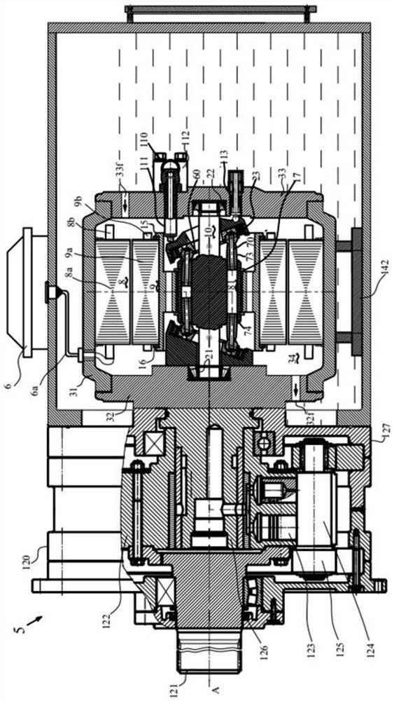
[0061] like Figures 2 to 5 As shown, it is a preferred embodiment of the high-power compact electro-hydraulic wind generator set 5 of the present invention. In the preferred embodiment shown, the electro-hydraulic wind generator set 5 is a shaft-supported structure, including an impeller assembly, hydraulic The pump assembly, the fuel tank, and the electro-hydraulic integrated machine assembly accommodated in the cavity 141 of the fuel tank casing, the electro-hydraulic integrated machine assembly including the generator casing assembly and the casing cavity 34 accommodated in the generator casing assembly Inside the generator assembly and hydraulic motor assembly, the generator assembly includes a rotor assembly 9 and a stator assembly 8, the hydraulic motor assembly includes a distribution sliding plate pair and a plunger pair, the hydraulic pump assembly is from the oil tank housing. The cavity 141 and / or the housing cavity 34 of the generator absorbs oil, the impeller ass...

Embodiment 2

[0094] like Figure 13 As shown, the difference from Embodiment 1 is the number and structure of the cylinders in the hydraulic motor assembly.

[0095] Specifically, the hydraulic motor assembly includes two cylinders 80 , the cylinders 80 have a cylindrical configuration with a circular cross-section in the radial direction, and are accommodated in the cavity of the rotating drum 11 , and the cylinders 80 have There are a plurality of plunger holes 81 evenly distributed in the circumferential direction of the central axis of the cylinder body and a spindle assembly hole for accommodating the main shaft 10 at the center. Preferably, the number of the plunger holes 81 is generally set to 7 or 9.

[0096] Further, the main shaft 10 passes through the main shaft assembly hole of the cylinder block 80 and is connected to the cylinder block 80 by means of connecting keys on the outer peripheral surface of the shaft. 10 on. The central part of the main shaft 10 is provided with ...

Embodiment 3

[0099] like Figure 15 As shown, the difference from Embodiment 1 is that the oil suction path of the hydraulic pump assembly is different.

[0100] Specifically, the front end cover 32 in the generator housing assembly is further provided with a front end cover oil inlet channel 32a, one end of the front end cover oil inlet channel 32a is open to the casing cavity 34, and the other end is connected to the hydraulic pump assembly. The shaft low pressure port 126a is communicated with, the rear end cover 33 is provided with a rear end cover oil inlet 33a, one end of the rear end cover oil inlet 33a is communicated with the tank housing cavity 141, and the other end is connected with the housing cavity 34 .

[0101] It can be seen from this that the oil suction path of the hydraulic pump is as follows. Oil is sucked through the three friction pairs of the hydraulic motor assembly, the stator assembly and the rotor assembly of the generator assembly, and through the oil inlet p...


PUM


Abstract

The invention discloses a high-power compact electro-hydraulic wind generating set assembly which comprises an impeller assembly, a hydraulic pump assembly, an oil tank and an electro-hydraulic all-in-one machine assembly contained in a cavity of an oil tank shell. The electro-hydraulic all-in-one machine assembly comprises a generator shell assembly, a rotor assembly, a stator assembly and a hydraulic motor assembly, the rotor assembly, the stator assembly and the hydraulic motor assembly are contained in a shell cavity of the generator shell assembly, the hydraulic pump assembly sucks oil from an oil tank shell cavity and/or a generator shell cavity, and the impeller assembly is connected with the hydraulic pump assembly. The hydraulic pump assembly outputs high-pressure oil to drive a hydraulic motor assembly and a rotor assembly in the electro-hydraulic all-in-one machine assembly to rotate, and power generation is achieved. The wind generating set disclosed by the invention is high in electro-hydraulic fusion, and has the characteristics of high power, compact structure, small volume, light weight, low noise, high efficiency, energy conservation, self-cooling, high power density, high reliability, long service life and the like.

Description

technical field [0001] The invention belongs to the technical field of power generation, and particularly relates to a high-power compact electro-hydraulic wind generator set assembly in the field of wind power. Background technique [0002] As a clean and renewable energy, wind energy is an important support for my country's energy transformation. At present, wind power generation is one of the most mature, large-scale development conditions and commercialized development prospects. Wind power generation has obvious advantages in changing the energy structure and alleviating environmental pollution, and has attracted more and more attention at home and abroad. , countries around the world have attached great importance to the development of wind power. After 2025, the average annual new wind power installed capacity will be no less than 60GW. The converted investment amount is calculated at 7,000-10,000 yuan / kw. In the future, the annual new investment in wind power in my ...

Claims


Application Information

Patent Timeline
IPC IPC(8): F16H39/42F16H39/00F15B1/02F15B11/16F15B13/06F15B21/041F03D9/25F03D15/00
CPCF16H39/42F16H39/00F15B1/024F15B11/161F15B13/06F15B21/041F03D9/25F03D15/00F05B2260/406
Inventor 钟彪
Owner 钟彪
Why Eureka
Try Eureka