Check patentability & draft patents in minutes with Patsnap Eureka AI!

Terahertz near-field optical path debugging device and debugging method thereof

A near-field light and terahertz technology, applied in measuring devices, color/spectral characteristic measurement, and material analysis through optical means, to improve detection efficiency, achieve strict calibration, and reduce debugging difficulty

Pending Publication Date: 2022-07-29
YISHENG SCI INSTR (JIAXING) CO LTD
View PDF5 Cites 0 Cited by
  • Summary
  • Abstract
  • Description
  • Claims
  • Application Information

AI Technical Summary

Problems solved by technology

[0006] The purpose of the present invention is to solve or at least alleviate the problems existing in the prior art

Method used


Image

  • Terahertz near-field optical path debugging device and debugging method thereof

Examples


Embodiment 1

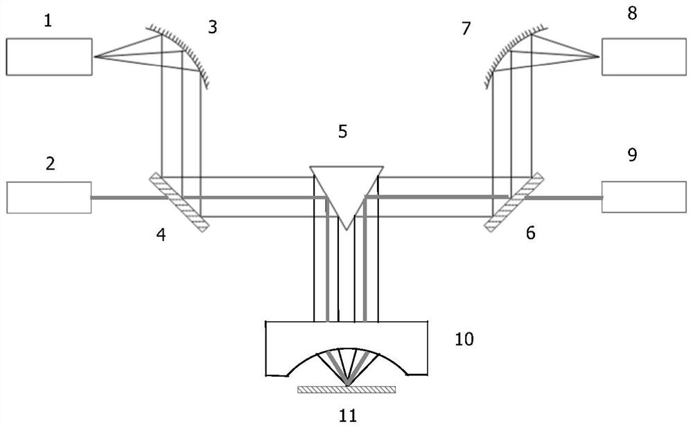
[0041] The present invention provides a terahertz near-field optical path debugging device. figure 1 , including:

[0042] Two first visible light point light sources 1 and second visible light point light sources 8 arranged opposite to each other are used to simulate terahertz point light sources and provide visible outgoing light;

[0043] The first collimated visible laser source 2 and the second collimated visible laser source 9 are used to provide two visible guide laser beams;

[0044] Two sets of optical path adjustment systems are used to adjust the visible outgoing light of the visible point light source into a collimated beam and realize coaxial transmission with the guiding laser; the optical path adjustment system includes: a first leveling mirror 3 and a second leveling mirror 7, It is used to level the emitted light of the visible point light source into a collimated beam and change its transmission direction. In this embodiment, the first leveling mirror 3 and ...

Embodiment 2

[0053] The present invention also provides a debugging method of the terahertz near-field optical path debugging device, comprising the following steps:

[0054]S1. Turn on the first visible light point light source 1 and the second visible light point light source 8 that are opposite to each other, provide two visible light point lights, and pass the first leveling mirror 3 and the second leveling mirror 7 The emitted visible light point light Adjust the collimated light beam, then, the two beams of point light source light are reflected and emitted through the first ITO conductive glass 4 and the second ITO conductive glass 6 respectively;

[0055] S2, turn on the first collimated visible laser source 2 and the second collimated visible laser source 9, and provide two beams of visible guide laser beams and two beams of point light source outgoing light coaxial transmission;

[0056] S3, two beams of visible guiding laser light and two beams of point light source outgoing lig...


PUM


Abstract

The invention provides a terahertz near-field optical path debugging device and a debugging method thereof, and aims to solve the problems that in terahertz near-field optical path debugging, the overlap ratio of guide laser and terahertz waves is difficult to guarantee, the signal debugging difficulty is large, and the detection efficiency is low. Comprising two visible light point light sources used for simulating terahertz point light sources; the two collimation visible laser sources are used for providing two beams of visible guide laser; the two groups of light path adjusting systems are used for adjusting emergent light of the visible light point light source into collimated light beams and realizing coaxial transmission with the guide laser; the reflecting mirror is arranged at the emergent ends of the two groups of light path adjusting systems; the concave reflecting mirror is used for focusing the collimated light beam on release paper; the release paper is used for simulating a needle point to receive the focusing light spot and scatter the focusing light spot; a terahertz point light source; a terahertz detector; provided is an atomic force microscope. The terahertz near-field optical path calibration device is especially suitable for strict calibration of a terahertz near-field optical path, and has high social use value and application prospect.

Description

technical field [0001] The invention relates to the technical field of near-field optical path debugging, in particular to a terahertz near-field optical path debugging device and a debugging method thereof. Background technique [0002] The band of terahertz waves can cover the characteristic spectrum of substances such as semiconductors, plasmas and biological macromolecules, and has great application value in the fields of physics, chemistry and life sciences. The wavelength of the terahertz light source is about 300um. Due to the existence of the diffraction limit, the optical spatial resolution of the terahertz far-field measurement system is generally limited to about 150um. The accuracy of this result is not sufficient for materials research requiring nanometer resolution. The terahertz near-field optical microscope can break through the diffraction limit and achieve a spatial resolution of about 30 nm, which provides a good solution to this problem. [0003] Due to...

Claims


Application Information

Patent Timeline
IPC IPC(8): G01N21/3581G01N21/25G01N21/27
CPCG01N21/3581G01N21/255G01N21/274
Inventor 李净张宇田悦马诚杰沈敏敏王城程
Owner YISHENG SCI INSTR (JIAXING) CO LTD
Features
  • R&D
  • Intellectual Property
  • Life Sciences
  • Materials
  • Tech Scout
  • Unparalleled Data Quality
  • Higher Quality Content
  • 60% Fewer Hallucinations
Learn More