Four-section type cable partial discharge source double-end monitoring and positioning method

A cable partial discharge and positioning method technology, which is applied in the direction of fault location and dielectric strength test, can solve the problems of large ambiguity of positioning results, signal attenuation, and positioning accuracy constraints, and reduce signal overlap, attenuation and scattering , to reduce the effect of signal attenuation

Active Publication Date: 2022-07-29
NORTH CHINA ELECTRIC POWER UNIV (BAODING)
View PDF8 Cites 0 Cited by
  • Summary
  • Abstract
  • Description
  • Claims
  • Application Information

AI Technical Summary

Problems solved by technology

Time domain reflectometry, as the mainstream PD online positioning technology, has the advantages of convenient application and rapid positioning. However, considering that PD signals will be affected by attenuation and scattering during long-distance cable propagation, single-ended TDR The method is more suitable for partial discharge on-line positioning of short-distance cables; the double-terminal time difference of arrival method overcomes the shortcomings of single-terminal monitoring, and is suitable for partial discharge detection of long-distance cables, but the positioning accuracy is restricted by the synchronization of the double-terminal time system
[0003]Comparative analysis of the positioning accuracy of various intrinsic point identification schemes based on peak, threshold, energy criterion (EC) or information criterion (AIC) found that peak detection The energy criterion method and the energy criterion method have high application stability, but their positioning accuracy is still restricted by factors such as noise level and partial discharge waveform.
In recent years, industry experts and scholars have proposed a variety of new cable PD on-line location technologies: the amplitude-frequency matching method calculates the specific location of PD sources by comparing the characteristics of PD signals collected at different locations in the time and frequency domains. position, can be applied to the partial discharge detection of long cables, but its positioning results are more ambiguous, and are more suitable for pre-screening of cable defect positions; rise time and transfer function positioning technology uses the corresponding relationship between rise time and cable system transfer function , the location of the PD source can be determined by monitoring and analyzing the PD signal at one end of the cable. However, the realization of this method depends on the knowledge base of the rise time and transfer function of the original PD pulse based on fixed parameters established in advance; The terminal phase difference positioning technology realizes the positioning of PD by analyzing the phase difference between the incident wave and the reflected wave in the frequency domain, avoids the estimation of the signal arrival time, and weakens the influence of noise level and pulse waveform on the positioning accuracy, but this method Faced with the problem of severe signal attenuation in long-distance cables similar to TDR technology; the double-ended phase difference partial discharge positioning technology is suitable for partial discharge detection of long cables, but this method is the same as the previous single-ended solution. The duration of the entire cable transmission is used as the interval for PD pulse analysis. On the one hand, this processing increases the algorithm processing load, and on the other hand, it introduces redundant noise signals into the phase analysis, which affects the accuracy of PD positioning results.

Method used


Image

  • Four-section type cable partial discharge source double-end monitoring and positioning method
  • Four-section type cable partial discharge source double-end monitoring and positioning method
  • Four-section type cable partial discharge source double-end monitoring and positioning method

Examples


Embodiment Construction

[0023] It should be noted that the embodiments in the present application and the features of the embodiments may be combined with each other in the case of no conflict. The present application will be described in detail below with reference to the accompanying drawings and in conjunction with the embodiments.

[0024] It should be noted that the steps shown in the flowcharts of the accompanying drawings may be executed in a computer system, such as a set of computer-executable instructions, and, although a logical sequence is shown in the flowcharts, in some cases, Steps shown or described may be performed in an order different from that herein.

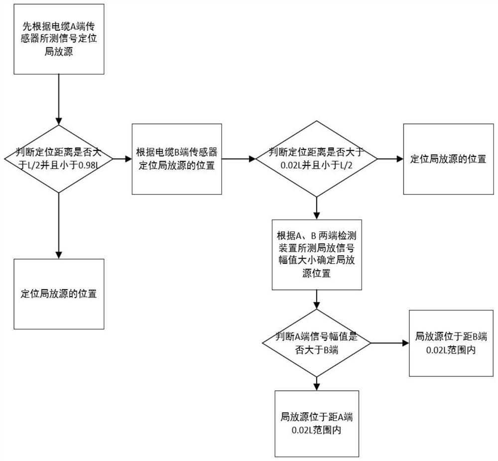
[0025] like figure 1 As shown, this embodiment provides a four-segment cable partial discharge source double-ended monitoring and positioning method, including the following steps:

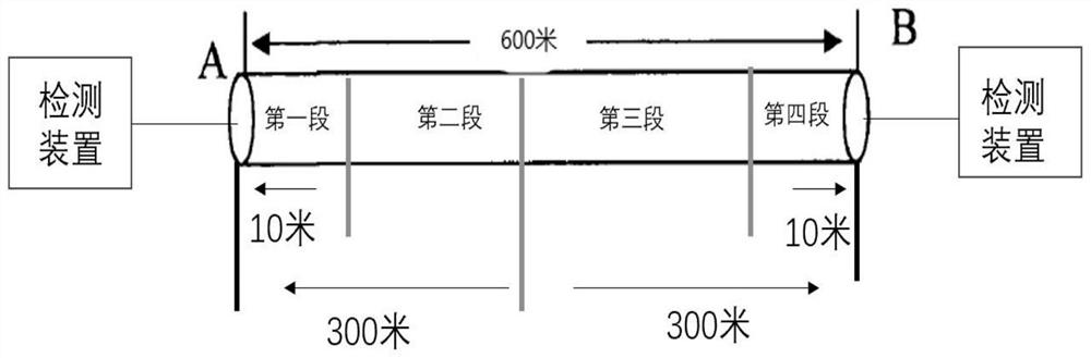
[0026] Monitoring devices are used on the left and right sides of the cable to obtain the partial discharge signal of the cable;

[0027] The cable...


PUM


Abstract

The invention discloses a four-section type cable partial discharge source double-end monitoring and positioning method. The method comprises the steps that the left side and the right side of a cable acquire partial discharge signals of the cable through monitoring devices; the cable is divided into a left part and a right part with the central axis as the standard, the left part and the right part are not equally divided into two areas and are symmetrically divided along the central axis, four areas are obtained, and the position of the area where a partial discharge source belongs is judged according to the obtained partial discharge signals of the cable based on the four areas. According to the invention, double-end monitoring is adopted, so that partial discharge signals can be monitored more easily; the partial discharge source position problem can be reduced by adopting a cable segment processing mode; acquired partial discharge signals are accumulated by adopting an energy accumulation curve, so that environmental noise can be reduced to a great extent, and then a time difference between an incident wave and a reflected wave is calculated by utilizing a wavelet transform mode and an autocorrelation analysis mode. The influence of environmental noise on the time difference can be avoided to a great extent, and the accuracy of time difference estimation is improved.

Description

technical field [0001] The invention belongs to the technical field of cable partial discharge detection, and in particular relates to a four-segment cable partial discharge source double-end monitoring and positioning method. Background technique [0002] The partial discharge phenomenon of power cables is the leading cause of the deterioration of the cable insulation material and will gradually lead to the final damage of the cable. Therefore, the monitoring and positioning of partial discharge has always been highly concerned by cable researchers at home and abroad. As the mainstream PD online positioning technology, time domain reflectometry has the advantages of convenient application and rapid positioning. However, considering that PD signals will be affected by attenuation and scattering during the propagation of long-distance cables, single-ended TDR The method is more suitable for PD online positioning of short-distance cables; the double-ended arrival time differen...

Claims


Application Information

Patent Timeline
Patent Type & Authority Applications(China)
IPC IPC(8): G01R31/12G01R31/08
CPCG01R31/1272G01R31/086
Inventor 孙春雨唐志国
Owner NORTH CHINA ELECTRIC POWER UNIV (BAODING)
Why Eureka
Try Eureka