
Lithium battery and assembly method

A technology of lithium batteries and batteries, which is applied in the manufacture of lithium batteries, secondary batteries, non-aqueous electrolyte batteries, etc. It can solve problems such as poor bonding between tabs and collector plates, affecting discharge current, and large battery resistance. To achieve the effect of strengthening connection, precise connection and increasing current

Pending Publication Date: 2022-07-29
英能基(成都)科技有限公司
View PDF0 Cites 1 Cited by
  • Summary
  • Abstract
  • Description
  • Claims
  • Application Information

AI Technical Summary

Problems solved by technology

Since the tab is located below the current collecting plate, spot welding is performed from above the current collecting plate during welding, and the position of the tab is in the blind area of ​​vision. Accurately judge the position of the tabs, often cannot weld the tabs on the collector plate in all aspects, and the battery resistance is large, which will affect the discharge current

Method used


Image

  • Lithium battery and assembly method
  • Lithium battery and assembly method
  • Lithium battery and assembly method

Examples


Embodiment 1

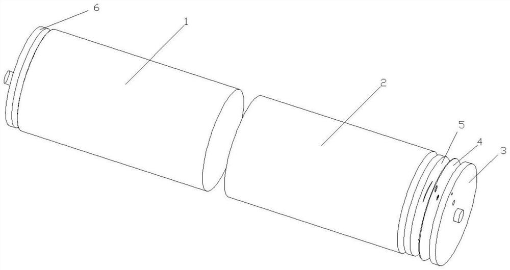
[0057] A lithium battery, characterized in that, comprising:

[0058] Housing 1 with positive and negative poles;

[0059] A cell 2 with a positive side and a negative side;

[0060] Positive cover plate 3;

[0061] Positive insulating sheet 4;

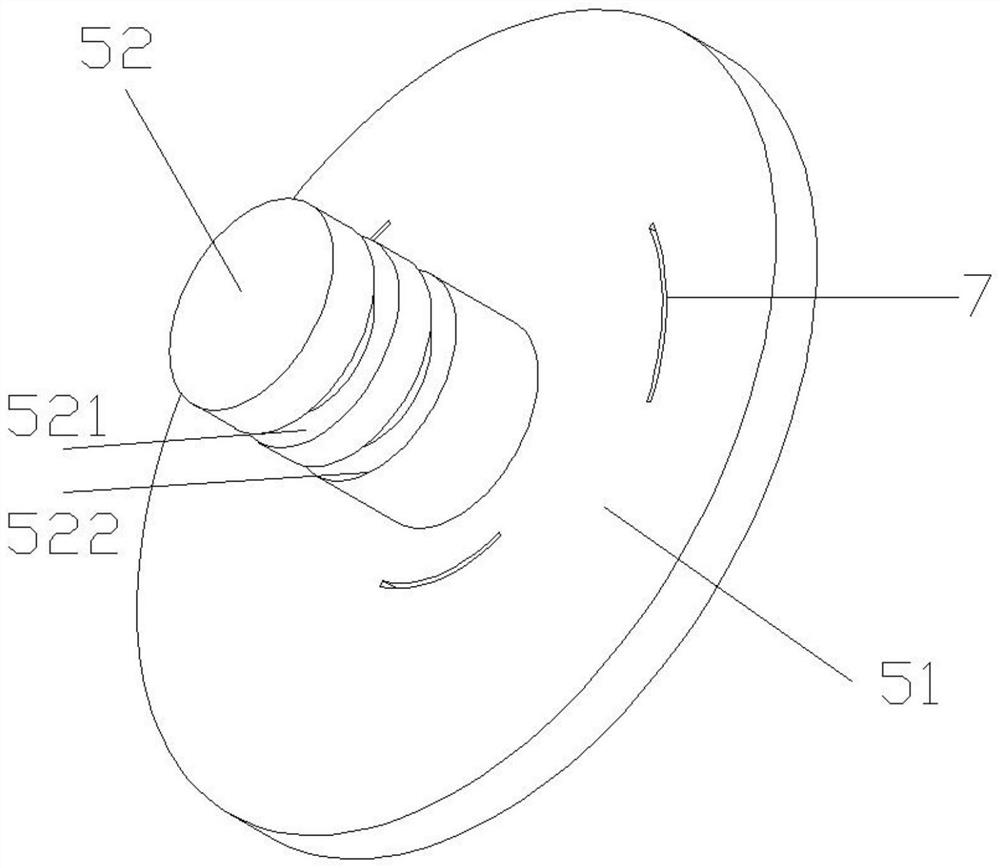
[0062] The positive electrode current collecting structure 5 includes a positive electrode current collecting disk 51 and a positive electrode current collecting column 52;

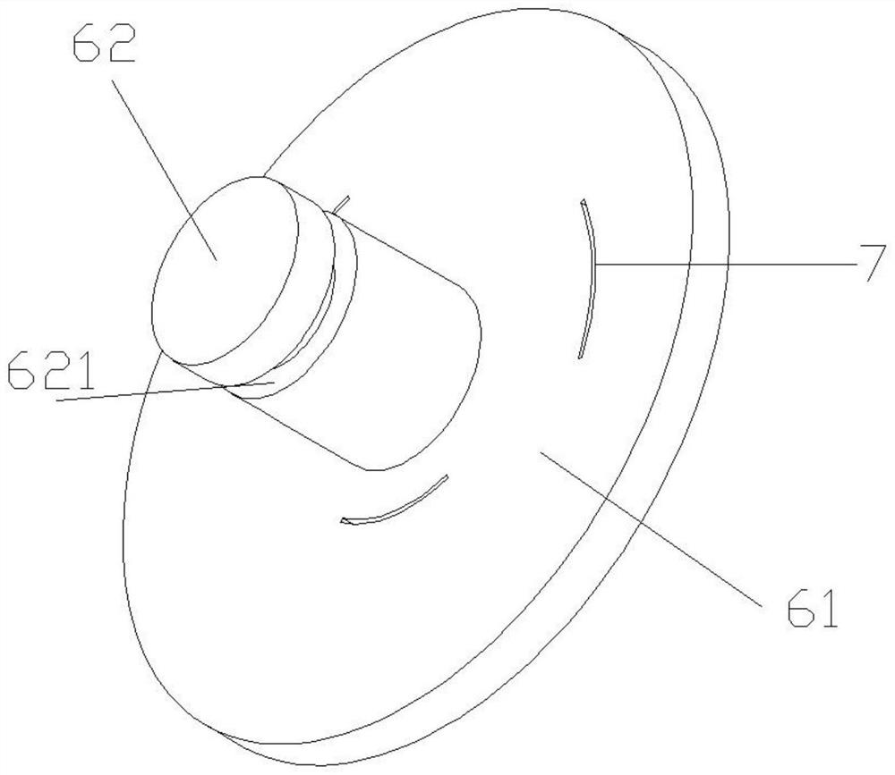
[0063] The negative electrode current collecting structure 6 includes a negative electrode current collecting disk 61 and a negative electrode current collecting column 62;

[0064] The casing 1 is a hollow cylindrical tube, the positive end is open, the negative end is closed, and an assembly through hole A is provided in the center of the surface of the negative end;

[0065] Wherein, the positive electrode current collecting column 52 is arranged in the center of the positive electrode current collecting disk 51, and is connected with the positive electrod...

Embodiment 2

[0074] The positive electrode current collecting disk 51 and the negative electrode current collecting disk 61 both include long arc holes 7, the long arc holes 7 are used for the electrode lugs to pass through, and the distribution positions correspond to the electrode lugs one-to-one.

[0075] In the prior art, the electrode tabs of the battery cores are closely attached along the lower surface of the current collecting plate, and the contacts are spot welded on the upper surface of the current collecting plate by means of laser welding. Since the tabs are located below the collector plate, spot welding is performed from the top of the collector plate during welding, and the tab position is in the blind area of ​​the field of view. To accurately determine the position of the tabs, it is often impossible to weld the tabs on the current collecting plate in all directions, and the battery resistance is large, which affects the discharge current.

[0076] In this embodiment, the...

Embodiment 3

[0079] The positive electrode current collecting column 52 includes a first groove 521 and a second groove 522, and the negative electrode current collecting column 62 includes a third groove 621;

[0080] Wherein, the first groove 521 is used for assembling the positive cover plate 3, the second groove 522 is used for assembling the positive insulating sheet 4, and the third groove 621 is used for assembling the negative terminal of the casing;

[0081] The distance between the first groove 521 and the second groove 522 is 2 mm.

[0082] In this embodiment, grooves are arranged in the current collecting column to make the connection between the current collecting column and the cover plate, the insulating sheet and the casing more stable. During the use of the battery, the internal electrolyte reaction will generate gas and cause the battery to expand. A pressure relief valve is often set on the positive electrode cover plate of the battery. The positive electrode cover plate...


PUM

PropertyMeasurementUnit
widthaaaaaaaaaa
lengthaaaaaaaaaa

Abstract

The lithium battery comprises a shell, a battery cell, a positive electrode cover plate, a positive electrode insulating sheet, a positive electrode current collecting structure and a negative electrode current collecting structure, the shell is a hollow cylindrical tube, the positive electrode end is open, the negative electrode end is closed, an assembly through hole A is formed in the center of the surface of the negative electrode end, the positive electrode cover plate is installed on the positive electrode current collecting structure, and the positive electrode insulating sheet is installed on the battery cell. The positive electrode insulation sheet is installed on the positive electrode current collecting structure and located between the positive electrode cover plate and the positive electrode current collecting structure, the battery cell positive electrode face is welded to the positive electrode current collecting structure, the battery cell negative electrode face is welded to the negative electrode current collecting structure, and the negative electrode current collecting structure is connected with the shell negative electrode end through an assembly through hole A. The invention has the beneficial effects that the current collecting columns are arranged on the current collecting plates, so that the connection between the current collecting columns and the current collecting plates is enhanced, the internal resistance of the battery is further reduced, and the current is increased; and the insulating sheet and the cover plate are directly mounted on the current collecting column, so that the welding steps are reduced, and the technological process is simplified.

Description

technical field [0001] The invention belongs to the technical field of lithium batteries, relates to a lithium battery assembly technology, and in particular relates to a lithium battery and an assembly method. Background technique [0002] Lithium battery is a battery in which lithium metal or lithium alloy is used as negative electrode material, manganese dioxide is used as positive electrode, and lithium salt is dissolved in organic solvent as electrolyte. Due to the advantages of high current, high energy density and high life expectancy, lithium batteries stand out among many types of batteries and are widely used in various devices in various scenarios. [0003] Most of the existing lithium batteries adopt an assembly form in which a current collecting column is arranged on the cover plate, the current collecting plate is welded with the cell, and the current collecting plate is welded with the current collecting column as a whole. In this assembly method, the cover p...

Claims


Application Information

Patent Timeline
Patent Type & Authority Applications(China)
IPC IPC(8): H01M10/052H01M10/04
CPCH01M10/052H01M10/0404
Inventor 刘昌国黎明
Owner 英能基(成都)科技有限公司
Learn More