Phased-array antenna, microwave hyperthermia equipment and equipment control method
A phased array antenna and controller technology, which is applied in antennas, resonant antennas, antenna arrays, etc., can solve the problems of uneven heat dissipation of biological tissues, poor microwave focusing effect, and low microwave focusing accuracy, and achieve good microwave focusing effect , Good cooling effect, uniform cooling effect
- Summary
- Abstract
- Description
- Claims
- Application Information
AI Technical Summary
Problems solved by technology
Method used
Image
Examples
Embodiment 1
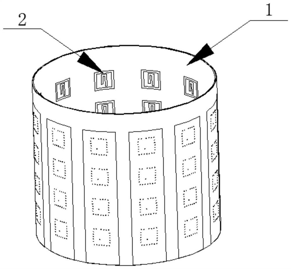
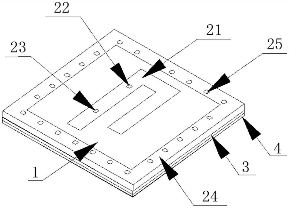
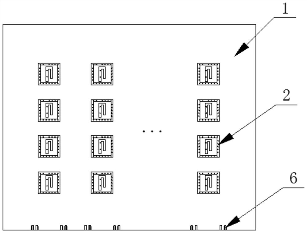
[0029] see attached Figures 1 to 4. A phased array antenna includes a dielectric substrate 1, a feeding network and several microstrip patch antennas 2; the dielectric substrate 1 is cylindrical in shape; the bottom of the dielectric substrate 1 is provided with a bottom plate; the dielectric substrate 1 The side wall of 1 is provided with several antenna arrays arranged around the center of the dielectric substrate 1; the antenna array includes several microstrip patch antennas 2 arranged from top to bottom; The patch antenna 2 is fed with a radio frequency signal. It can be seen from the above structure that the dielectric substrate 1 is the dielectric substrate carrying the microstrip patch antenna 2 and the feeding network. It is made of Somos WaterClearUltra 10122 photosensitive resin material developed by DSM in the Netherlands. The constant is about 3.1, the total thickness is about 3mm, and it can be manufactured using 3D printing technology. The shape of the diele...
Embodiment 2
[0031] see attached Figures 1 to 6 . A phased array antenna includes a dielectric substrate 1, a feeding network and several microstrip patch antennas 2; the dielectric substrate 1 is cylindrical in shape; the bottom of the dielectric substrate 1 is provided with a bottom plate; the dielectric substrate 1 The side wall of 1 is provided with several antenna arrays arranged around the center of the dielectric substrate 1; the antenna array includes several microstrip patch antennas 2 arranged from top to bottom; The patch antenna 2 is fed with a radio frequency signal. It can be seen from the above structure that the dielectric substrate 1 is the dielectric substrate carrying the microstrip patch antenna 2 and the feeding network. It is made of Somos WaterClearUltra 10122 photosensitive resin material developed by DSM in the Netherlands. The constant is about 3.1, the total thickness is about 3mm, and it can be manufactured using 3D printing technology. The shape of the diel...
Embodiment 3
[0037] see attached Figures 1 to 6 . A phased array antenna includes a dielectric substrate 1, a feeding network and several microstrip patch antennas 2; the dielectric substrate 1 is cylindrical in shape; the bottom of the dielectric substrate 1 is provided with a bottom plate; the dielectric substrate 1 The side wall of 1 is provided with several antenna arrays arranged around the center of the dielectric substrate 1; the antenna array includes several microstrip patch antennas 2 arranged from top to bottom; The patch antenna 2 is fed with a radio frequency signal. It can be seen from the above structure that the dielectric substrate 1 is the dielectric substrate carrying the microstrip patch antenna 2 and the feeding network. It is made of Somos WaterClearUltra 10122 photosensitive resin material developed by DSM in the Netherlands. The constant is about 3.1, the total thickness is about 3mm, and it can be manufactured using 3D printing technology. The shape of the diel...
PUM
| Property | Measurement | Unit |
|---|---|---|
| Thickness | aaaaa | aaaaa |
Abstract
Description
Claims
Application Information
 - R&D
- Intellectual Property
- Life Sciences
- Materials
- Tech Scout
- Unparalleled Data Quality
- Higher Quality Content
- 60% Fewer Hallucinations
Browse by: Latest US Patents, China's latest patents, Technical Efficacy Thesaurus, Application Domain, Technology Topic, Popular Technical Reports.
© 2025 PatSnap. All rights reserved.Legal|Privacy policy|Modern Slavery Act Transparency Statement|Sitemap|About US| Contact US: help@patsnap.com


