Speed regulation controller for DC motor of elevator door

A speed control controller and elevator technology, which is applied to elevators in buildings, transportation and packaging, etc., can solve the problems of high cost, many connecting wires, difficult installation and maintenance, etc., and achieve low cost, easy maintenance and debugging convenient effect

Inactive Publication Date: 2004-05-05
朱瑞智
View PDF0 Cites 0 Cited by
  • Summary
  • Abstract
  • Description
  • Claims
  • Application Information

AI Technical Summary

Problems solved by technology

Whether it is DC pulse width regulation or AC frequency conversion speed regulation, there are many connecting wires between them and the main control system of the elevator, which makes installation and maintenance difficult and costly

Method used


Image

  • Speed regulation controller for DC motor of elevator door
  • Speed regulation controller for DC motor of elevator door
  • Speed regulation controller for DC motor of elevator door

Examples


Embodiment Construction

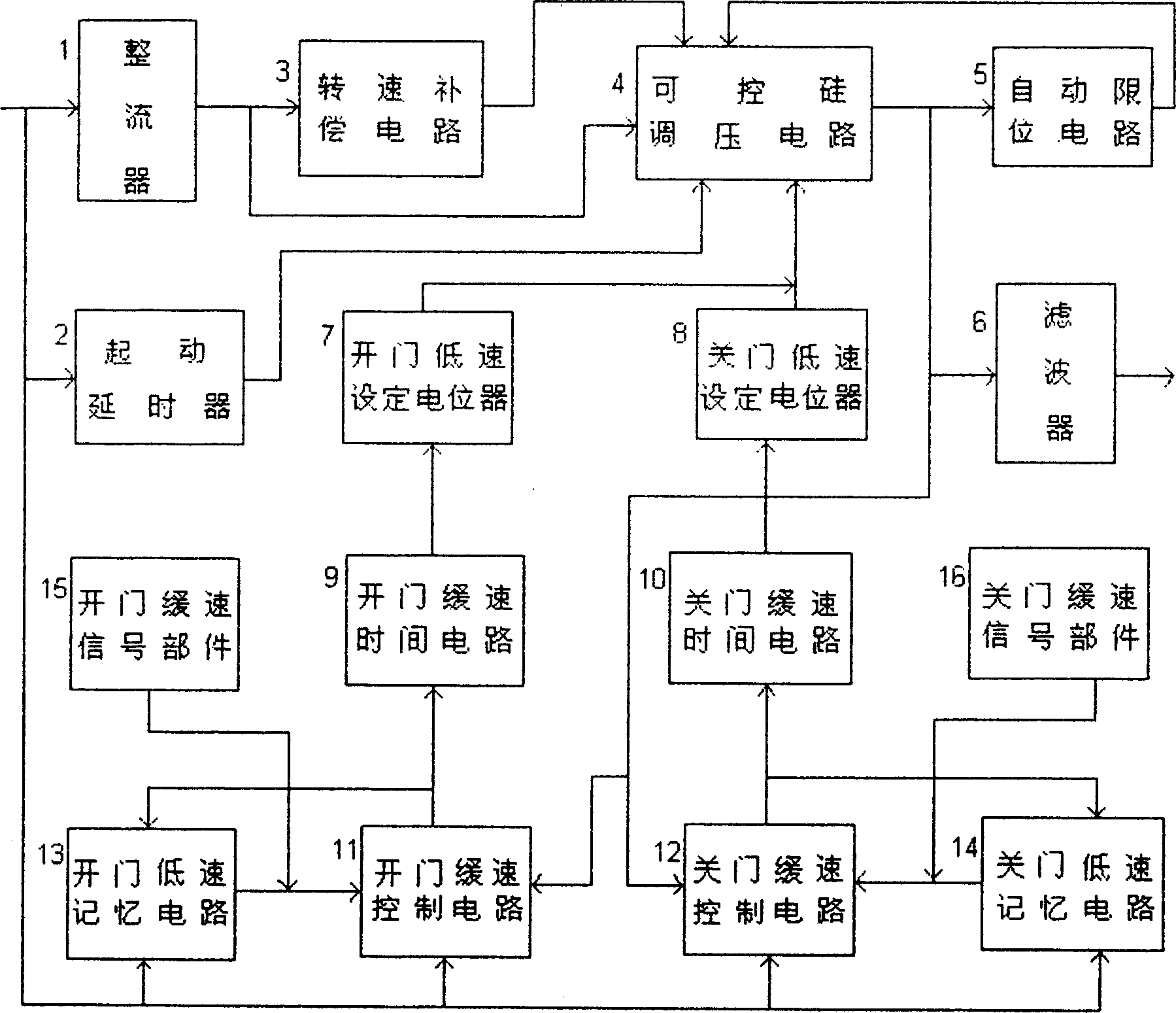
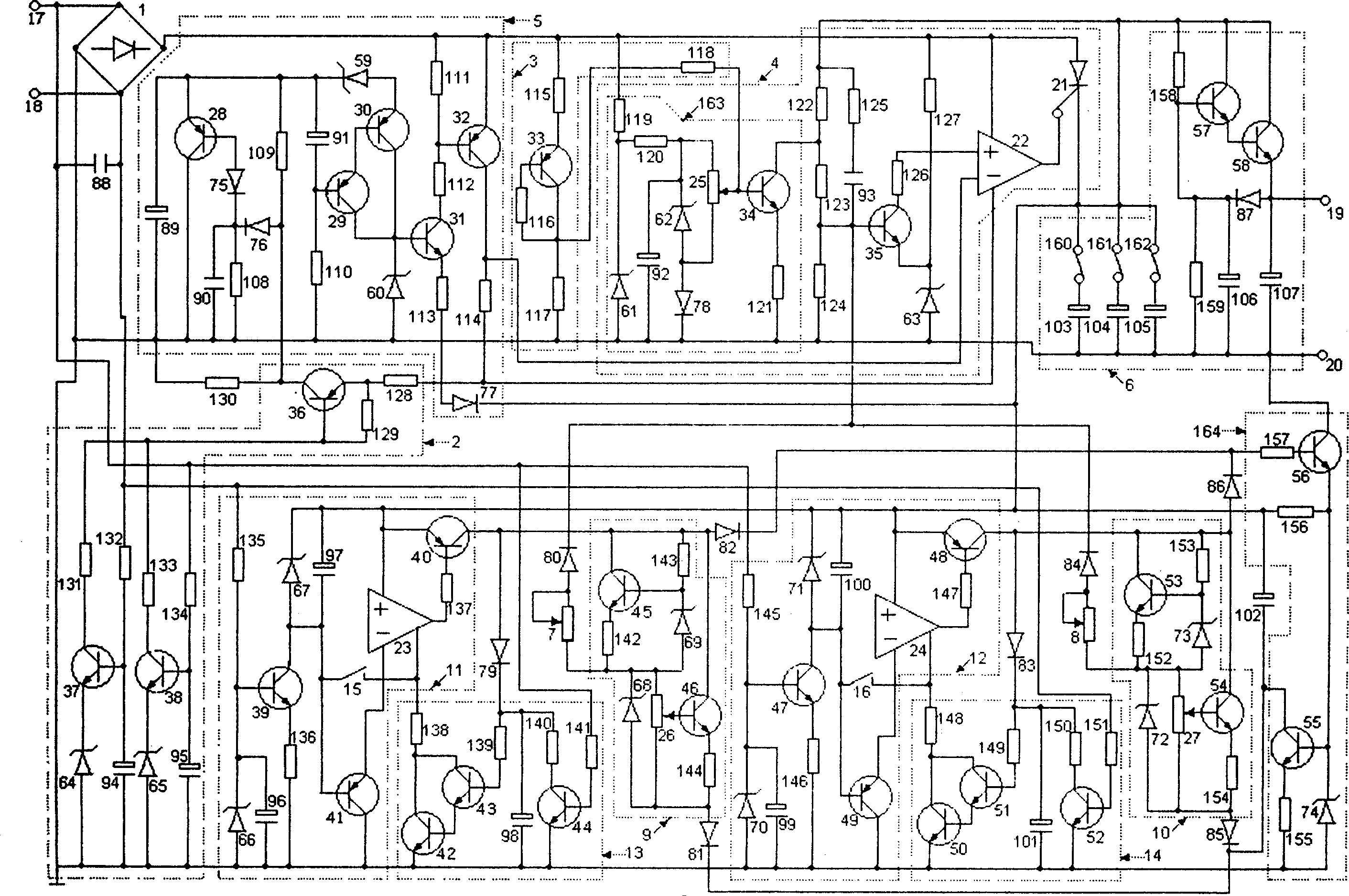
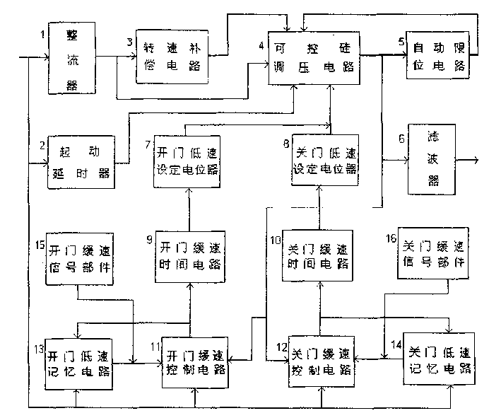
[0010] refer to figure 1 and figure 2The DC door machine speed regulating controller used for elevators, the thyristor voltage regulating circuit 4 is composed of a thyristor voltage stabilizing circuit and a steady current circuit 163 . The triode 35, the voltage stabilizing diode 63, the capacitor 93, the resistors 122-127, and the trigger circuit 22 constitute the sampling, amplification and synchronous trigger voltage stabilizing circuit of the thyristor 21. The triode 34, the voltage stabilizing diodes 61-62, the diode 78, the capacitor 92, the potentiometer 25, and the resistors 119-121 constitute the current stabilizing circuit 163. The two-stage diode voltage stabilizing source provides a voltage stabilizing source for the voltage regulating potentiometer 25 , and the diode 78 is the emitter junction temperature compensation element of the triode 34 . By adjusting the position of the base of the triode 34 on the tap of the potentiometer 25, a group of different and ...


PUM


Abstract

A speed controller for DC motor of elevator door is composed of the circuits for SCR voltage regulation, rotation speed compensation, slowering speed and automatic position limitation. Its power cord and signal line are connected to master control system of elevator. The exciting ends of motor is parallelly connected to power inputs. When input voltage is reversed, the rotation direction changes. The signal of slowering speed is generated by inductor. When controller receives a slowering-speed signal, the slowering-speed procedure is automatically performed according to parameter settings.

Description

technical field [0001] The invention relates to a DC motor speed regulation controller, more precisely, relates to a transistor circuit speed regulation controller used for elevator 110v DC door machine speed regulation. Background technique [0002] At present, in the elevator door opener control system, there are basically two speed regulation methods, one is DC pulse width regulation, that is, PWM DC control system, and the other is AC frequency conversion speed regulation, that is, VVVF AC control system. The structures of these two systems are relatively complicated, and the required working power supply voltage is high, and the support of a microcomputer or PLC is required, and it is difficult to install a speed measurement feedback device. When the speed measuring device is not used, there are many electrical switches used to obtain control signals, such as slow speed signal switches and limit signal switches. During the process of slowing down and limiting, these sw...

Claims


Application Information

Patent Timeline
IPC IPC(8): B66B13/14
Inventor 朱瑞智
Owner 朱瑞智
Why Eureka
Try Eureka