Hardware surface treatment device

A surface treatment device and hardware technology, which is applied to the device for coating liquid on the surface, the spray device, the surface pretreatment, etc., which can solve the problems of time-consuming, unsatisfactory treatment effect, and poor treatment efficiency. , to achieve the effect of improving the effect and efficiency

Active Publication Date: 2022-08-05
赣州嘉蓓乐实业发展有限公司
View PDF12 Cites 0 Cited by
  • Summary
  • Abstract
  • Description
  • Claims
  • Application Information

AI Technical Summary

Problems solved by technology

[0005] In order to overcome the above-mentioned prior art, the present invention cannot automatically process a plurality of hardware separately, the processing efficiency is relatively poor, and it takes a lot of time. At the same time, The treatment

Method used


Image

  • Hardware surface treatment device
  • Hardware surface treatment device
  • Hardware surface treatment device

Examples


Example Embodiment

[0034] Example 1

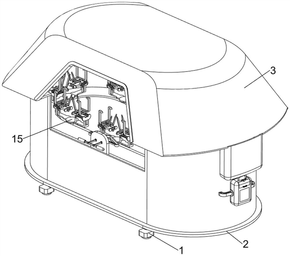
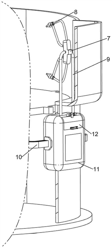
[0035] A five -gold surface processing device, such as Figure 1-4It shows that there are support blocks, fixed boards 2. outer frame 3, first fixation frame 4, first fixing frame 5, pump body 7, spray head 8, conveying tube 9, support board 10, leaflet box 11, blocking, blocking, blocking Board 12, clamping mechanism 15 and teleportation agency 14, the bottom bolt of the outer frame 3 with a fixed board 2, the left bottom and the bottom side of the right side of the fixed board 2 are also supporting block 1, support block 1, support The material of the block 1 is made of rubber, which can play a non -slip. The top side of the fixed board 2 has the first fixing frame 5, and the inner welded in the middle of the outer frame 3 has the first binding frame around the first fixing frame 5 4, the gap between the first fixed bit 4 and the first fixed frame 5 is named the first oriental slot 6, and there are two support plate 10 welded on the lower right side of the oute...

Example Embodiment

[0040] Example 2

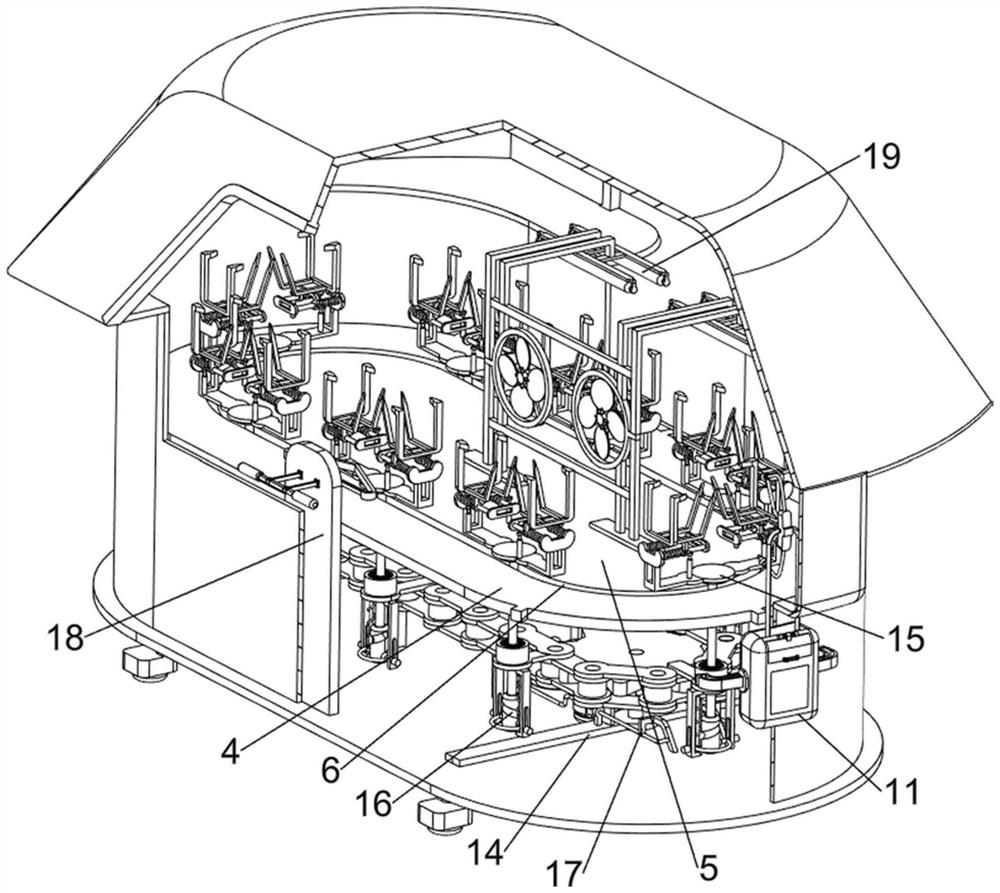
[0041] On the basis of Example 1, such as figure 2 and Figure 10 It also shows that the rotating mechanism 17 used to drive the clipped grip 155 rotation agency 17, the rotating mechanism 17 includes a fixed rod 171, arc -shaped rod 173, promoting ball 174, space cam 1741, first elastic component 175, and second torque spring 176, a second torque spring between the rotating rod 152 and the second positioning box 151, the bottom bolt of the rotor 152 is connected with space camsome 1741, the lower outside welding of the second positioning box 151 has a fixed rod 171, a fixed rod is fixed rod The third -oriented slot 172 is opened on both sides of the lower part of 171. The sliding type between the third -directional slot 172 is set with a arc rod 173, the arc -shaped rod 173 and the fixed rod 171 are connected to the first elastic piece 175 175 , The arc rod 173 is connected to the spatial cam 1741 sliding push ball 174.

[0042] like figure 2 As well as Figure 8...

Example Embodiment

[0044] Example 3

[0045] On the basis of Example 2, such as figure 2 As well as Figure 11 and Figure 12 It also includes the opening mechanism 18 that is used for the auxiliary clamping mechanism 15. The opening mechanism 18 includes a positioning board 181, handle 182, supporting rod 183, connected column 184 and second elastic parts 185, slide block 154 The lower part of the connection column 184, the front upper welding of the fixed board 2 has a positioning board 181, the upper sliding type of the positioning board 181 has a handle 182. The movement rod 183, the supporting rod 183 and the positioning board 181 are connected to the second elastic parts 185.

[0046] The operator promotes the supporting rod 183 backward by the handle 182, and the second elastic parts 185 stretch. The support rod 183 will squeeze the symmetrical pillar 184 during the movement of the backward movement. Move in the direction that is far away from each other. Connection column 184 movement will dri...


PUM


Abstract

The invention relates to a treatment device, in particular to a hardware surface treatment device. According to the hardware surface treatment device, multiple pieces of hardware can be automatically and separately treated, the treatment efficiency is high, and the effect is ideal. The hardware surface treatment device comprises a supporting block, a fixing plate, an outer frame, a first positioning frame, a first fixing frame and the like. The bottom side of the outer frame is connected with the fixing plate, the left bottom side and the right bottom side of the fixing plate are connected with the supporting blocks in a front-back symmetry mode, and the supporting blocks are made of rubber and can play an anti-skid role. Hardware is clamped through the clamping frame, so that the superficial area of the hardware is more exposed, comprehensive paint spraying operation is facilitated, meanwhile, the multiple pieces of hardware can be separately treated, a chain is driven by a motor to rotate, the hardware is made to rotate, and then paint spraying treatment can be conducted on the hardware one by one through a spray head; and the paint spraying treatment effect is improved.

Description

Technical field [0001] The invention involves a processing device, especially for a five -gold surface processing device. Background technique [0002] Hardware is a tool obtained by processing or casting gold, silver, copper, iron, and tin, and is a common item in life. Because of gold, silver, copper, iron and tin materials When contacting water and air, the surface will be rusted, causing a reduction of the service life of the hardware. Therefore, the surface of the hardware is needed. The existing spray paint treatment is mostly using a special treatment device to conduct the hardware. For processing, although these processing devices can be sprayed with hardware, the processing effect is not ideal. [0003] For example, the patent authorized public number is CN213255361U, and the announcement date of 20210525 is an efficient hardware surface spray painting equipment, including the spray paint machine on the body. The location is connected to a workbench, which is connected t...

Claims


Application Information

Patent Timeline
IPC IPC(8): B05B16/20B05B13/02B05D3/04
CPCB05B16/20B05B13/0242B05B13/0228B05B13/0292B05D3/0413Y02P70/10
Inventor 钟永福钟文婷钟文杰钟文斌
Owner 赣州嘉蓓乐实业发展有限公司
Why Eureka
Try Eureka