Image reconstruction method and device and electronic equipment

A technology of image reconstruction and image modeling, which is applied in image enhancement, image conversion, image data processing, etc., can solve the problem of motion artifact enhancement and achieve the effect of reducing motion artifact

Pending Publication Date: 2022-08-05
上海电气控股集团有限公司智惠医疗装备分公司
View PDF0 Cites 0 Cited by
  • Summary
  • Abstract
  • Description
  • Claims
  • Application Information

AI Technical Summary

Problems solved by technology

[0016] In order to solve the above problems, the purpose of the embodiments of the present invention is to provide an image reconstruction method, device and electronic equipment, at least to solve the problem of enhancing motion artifacts in the prior art

Method used


Image

  • Image reconstruction method and device and electronic equipment
  • Image reconstruction method and device and electronic equipment
  • Image reconstruction method and device and electronic equipment

Examples


Embodiment 1

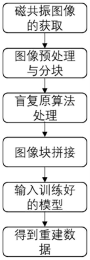
[0081] like figure 1 As shown, an image reconstruction method includes:

[0082] Perform block processing on the acquired magnetic resonance image;

[0083] After image acquisition, image preprocessing is performed first. For each magnetic resonance image, considering the spatial shift of the image itself, the original image needs to be divided into blocks for the estimation of block convolution kernels.

[0084] The PSF itself of the magnetic resonance system has spatial variability, so the motion and the blur kernel caused by the hardware estimated in this embodiment should not be global. The estimation of the blur kernel is required for each block.

[0085] At the same time, due to the locality of motion artifacts, this embodiment chooses to perform local aliasing processing on blocks to prevent unrecognized motion artifacts existing at edges and generation of ghosts caused by blocks.

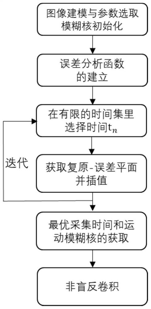
[0086] The image after block processing is processed by a blind restoration algorithm...

Embodiment 2

[0148] 1. Image preprocessing

[0149] After image acquisition, image preprocessing is performed first. For each magnetic resonance image, considering the spatial shift of the image itself, the original image needs to be divided into blocks for the estimation of block convolution kernels. like Figure 4a and Figure 4b shown.

[0150] The PSF itself of the magnetic resonance system has spatial variability, so the motion and the blur kernel caused by the hardware estimated in this embodiment should not be global. The estimation of the blur kernel is required for each block.

[0151] According to the characteristics of the magnetic resonance itself, there is a certain time interval between each phase encoding line during sequence encoding, while the sampling time interval of the frequency encoding line can be ignored to a certain extent. Due to the abnormal accumulation of phases and the acquisition time span , the appearance of motion artifacts are prevalent in the phase-en...

Embodiment 3

[0216] An image reconstruction device, comprising:

[0217] a preprocessing module, which is used to perform block processing on the acquired magnetic resonance image;

[0218] The restoration module is used to process the image after the block processing by the blind restoration algorithm to obtain a plurality of restored image blocks;

[0219] a splicing module for splicing a plurality of the image blocks;

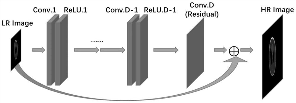
[0220] The reconstruction module is used to input the stitched image into the pre-trained reconstruction model to obtain the reconstructed image.


PUM


Abstract

The invention provides an image reconstruction method and device and electronic equipment, and the method comprises the steps: carrying out the partitioning of an obtained magnetic resonance image; processing the image subjected to block processing by adopting a blind restoration algorithm to obtain a plurality of restored image blocks; the plurality of image blocks are spliced; and inputting the spliced image into a pre-trained reconstruction model to obtain a reconstructed image. Block prediction and blind restoration are carried out on the images, finally splicing is carried out, reconstruction is carried out on the input pre-trained reconstruction model, the blind restoration can carry out motion blur restoration and high-resolution prediction by utilizing the estimation of a blur kernel, random trajectory prediction is carried out on motion artifacts of the medical images with spatial shift variation properties, and the motion artifacts of the medical images with spatial shift variation properties can be predicted. The artifact enhancement of the motion blur in the resolution reconstruction process is prevented, and the purpose of reducing the motion artifact and generating an enhancement effect is achieved.

Description

technical field [0001] The present invention relates to the technical field of magnetic resonance medical image processing, and in particular, to an image reconstruction method, device and electronic device. Background technique [0002] During magnetic resonance imaging, scan time is an important parameter. Scans that take minutes or even tens of minutes make it unbearable for patients to stay still for too long, which is prone to motion artifacts. At the same time, the signal-to-noise ratio is also an important parameter in most scans, but increasing the signal-to-noise ratio often requires increasing the slice thickness, thus reducing the spatial resolution of the signal. In order to speed up the scanning speed and improve the signal-to-noise ratio (Signal-to-Noise Ratio) (hereinafter referred to as SNR), during imaging, the imaging time is usually shortened by increasing the slice thickness and increasing the sampling step. But this often leads to lower image resolutio...

Claims


Application Information

Patent Timeline
Patent Type & Authority Applications(China)
IPC IPC(8): G06T3/40G06T5/00
CPCG06T3/4053G06T5/001G06T3/4038G06T5/002G06T2207/20201
Inventor 江昕阳吴振洲董霖张涛
Owner 上海电气控股集团有限公司智惠医疗装备分公司
Why Eureka
Try Eureka