Composite current collector, preparation method, electrode prepared from composite current collector and battery prepared from composite current collector
A current collector and electrode technology, applied in the direction of electrode carrier/current collector, final product manufacturing, sustainable manufacturing/processing, etc., to achieve the effects of improving thermal safety performance and acupuncture pass rate, reducing internal resistance, and low overall thickness
- Summary
- Abstract
- Description
- Claims
- Application Information
AI Technical Summary
Problems solved by technology
Method used
Image
Examples
preparation example Construction
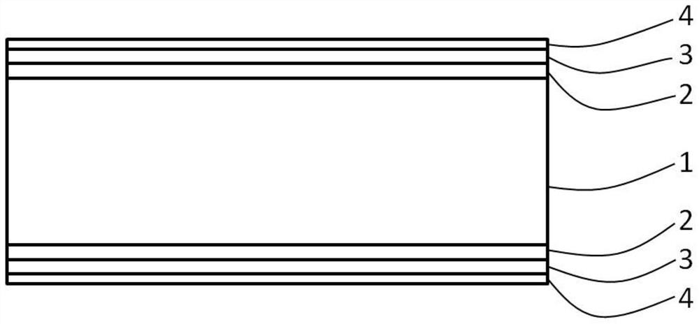
[0043] The application also discloses a preparation method of a composite current collector, comprising the following steps:
[0044] S1, preparing a first conductive metal layer 2 on both sides of the base layer 1;
[0045] S2, preparing a polymer PTC layer 3 on the outside of the first conductive metal layer 2;
[0046] S3 , preparing a second conductive metal layer 4 on the outside of the polymer PTC layer 3 .
[0047] Among them, the first conductive metal layer 2 and the second conductive metal layer 4 are prepared by one or more methods of vacuum evaporation coating, vacuum sputtering coating, vacuum electron beam coating, and electroplating; the polymer PTC layer 3 is made by coating or by spraying.
Embodiment 1
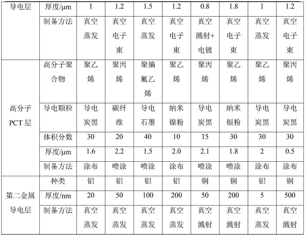
[0053] S1. Prepare a first conductive metal layer 2 on both sides of the base layer 1: select a 4.5 μm thick PET (polyethylene terephthalate) film as the base layer 1, and use a 4.5 μm thick base layer 1 on both sides of the base layer 1 By means of vacuum evaporation coating, a first metal conductive layer 2 with a thickness of 1 μm is formed, and the material of the first metal conductive layer 2 is aluminum;
[0054] S2. Prepare a polymer PTC layer 3 on the outside of the first conductive metal layer 2: apply the slurry of polyethylene + conductive carbon black particles on the outside of the first conductive metal layer 2, and dry to obtain a high Molecular PTC layer 3, the volume fraction of the conductive carbon black particles accounts for 30% of the polymer PTC layer 3;
[0055] S3. Prepare a second conductive metal layer 4 on the outside of the polymer PTC layer 3: obtain a second conductive metal layer 4 with a thickness of 20 nm on the outside of the polymer PTC lay...
Embodiment 2
[0057] S1, prepare the first conductive metal layer 2 on both sides of the base layer 1: select a 6 μm thick PET (polyethylene terephthalate) film as the base layer 1, and pass a vacuum on both sides of the 6 μm thick base layer 1 In the method of electron beam coating, a first metal conductive layer 2 with a thickness of 1.2 μm is formed, and the material of the first metal conductive layer 2 is aluminum;
[0058] S2. Prepare a polymer PTC layer 3 on the outside of the first conductive metal layer 2: spray the polypropylene+carbon fiber slurry on the outside of the first conductive metal layer 2, and dry to obtain a polymer PTC layer 3 with a thickness of 2.2 μm , the volume fraction of the carbon fiber accounts for 20% of the polymer PTC layer 3;
[0059] S3. Prepare a second conductive metal layer 4 on the outside of the polymer PTC layer 3: obtain a second conductive metal layer 4 with a thickness of 50 nm on the outside of the polymer PTC layer 3 by vacuum evaporation coa...
PUM
| Property | Measurement | Unit |
|---|---|---|
| thickness | aaaaa | aaaaa |
| thickness | aaaaa | aaaaa |
| thickness | aaaaa | aaaaa |
Abstract
Description
Claims
Application Information
 - R&D
- Intellectual Property
- Life Sciences
- Materials
- Tech Scout
- Unparalleled Data Quality
- Higher Quality Content
- 60% Fewer Hallucinations
Browse by: Latest US Patents, China's latest patents, Technical Efficacy Thesaurus, Application Domain, Technology Topic, Popular Technical Reports.
© 2025 PatSnap. All rights reserved.Legal|Privacy policy|Modern Slavery Act Transparency Statement|Sitemap|About US| Contact US: help@patsnap.com


