Ultrahigh frequency metal RFID signboard

A signage and ultra-high frequency technology, applied in the direction of identification devices, antennas, instruments, etc., can solve the problems of reducing impact resistance, unreadable, unreadable, etc., and achieve low processing accuracy requirements, improved mechanical properties, and improved The effect of machinability

Pending Publication Date: 2022-08-05
泰芯智能科技(昆山)有限公司
View PDF0 Cites 0 Cited by
  • Summary
  • Abstract
  • Description
  • Claims
  • Application Information

AI Technical Summary

Problems solved by technology

[0002] Metal identification plates are widely used in the fields of electronic products, home appliances, machinery and civil products, and have functions such as product description, product identification, instruction manual and product identification. The existing metal identification plates are limited by size, and the information contained is very Less, the information cannot be modified, it cannot be read after wear and tear, and the confirmation information must be read manually, which is not conducive to the inventory, information recording and information maintenance of the marked objects.
[0003] There are also some UHF RFID tags on the market. The signal of traditional UHF RFID will be covered by metal, that is, when a metal plate covers the RFID surface, the RFID signal will be covered by the metal plate, which will cause the RFID to be unreadable. or the read distance drops sharply to a few centimeters, such as figure 1 As shown, 01 is an RFID tag, 02 is a complete metal plate, and 05 is an RFID reader. When the RFID reader 05 sends out a signal 03 and encounters a complete metal plate 02, the metal plate 02 will cover the signal and reflect the reader signal 03 Return to 04, the RFID tag cannot receive the signal of the RFID reader 05 and cannot be activated, so that the RFID does not have any signal output to the RFID reader 05, so that the RFID reader 05 cannot read any information of the RFID tag 01
[0004] On the market, there are holes in the metal plate used as RFID feeder rings to solve the problem that the RFID cannot be read after the metal is covered, such as figure 2 As shown, 21 is an RFID tag, 22 is a perforated metal plate, and 23 is an RFID reader. The radio frequency signal 24 sent by the RFID reader 23 is passed through the hole 27 on the metal plate or passed as an excitation signal for the feeding excitation ring RFID tag 21, RFID is activated after receiving a signal or an excitation signal, and the signal 25 sent by the RFID is passed to the RFID reader 23 through the hole or the excitation ring 27, so that the RFID reader can read the RFID information, and 26 is the chip of the RFID tag , its position must be in the hole of the metal plate, and the relative position of the chip and the hole will affect the reading distance of the RFID, but this design needs to open a hole in the metal plate, and the RFID chip must be placed in a fixed position of the hole, resulting in RFID The chip is not protected by the metal plate, which affects the appearance and reduces the impact resistance of the RFID. At the same time, the relative position difference between the RFID and the opening will seriously affect the reading range of the RFID. In order to achieve a good and consistent reading range, the assembly needs to be strictly controlled. Accuracy, which in turn increases the difficulty of production and increases the production cost,

Method used


Image

  • Ultrahigh frequency metal RFID signboard
  • Ultrahigh frequency metal RFID signboard
  • Ultrahigh frequency metal RFID signboard

Examples


Embodiment Construction

[0025] The preferred embodiments of the present invention will be described in detail below with reference to the accompanying drawings, so that the advantages and features of the present invention can be more easily understood by those skilled in the art, and the protection scope of the present invention can be more clearly defined.

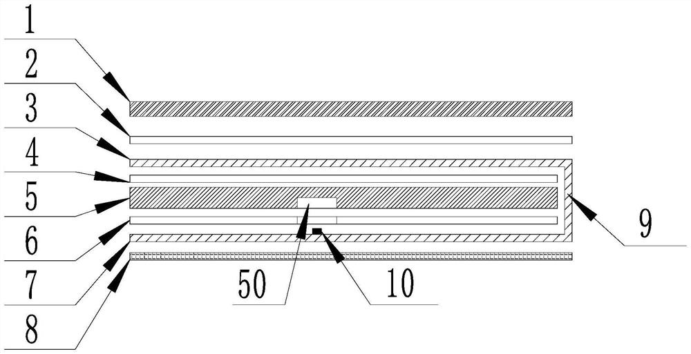
[0026] see Figure 3 to Figure 5 , the embodiments of the present invention include:

[0027] like image 3 As shown in the figure, an ultra-high frequency metal RFID identification plate includes a metal identification plate 1, a first double-sided adhesive layer 2, an antenna grounding layer 3, a second double-sided adhesive layer 4, and an insulating medium layer 5 in order from top to bottom. , the third double-sided adhesive layer 6, the antenna chip layer 7 and the fourth double-sided adhesive layer 8, the metal sign 1 is pasted to the antenna grounding layer 3 through the first double-sided adhesive layer 2, and the antenna grounding lay...


PUM


Abstract

The invention discloses an ultrahigh-frequency metal RFID (radio frequency identification) signboard, which sequentially comprises a metal signboard, a first double-faced adhesive tape layer, an antenna grounding layer, a second double-faced adhesive tape layer, an insulating medium layer, a third double-faced adhesive tape layer, an antenna chip layer and a fourth double-faced adhesive tape layer from top to bottom, and is characterized in that the metal signboard is adhered to the antenna grounding layer through the first double-faced adhesive tape layer; the antenna grounding layer and the antenna chip layer are separated by filling an insulating medium layer, the antenna chip layer is adhered to a managed object through a fourth double-faced adhesive tape layer, the microstrip antenna is characterized in that the antenna grounding layer and the antenna chip layer are conducted through a side face conduction layer to form a microstrip antenna structure, a chip is arranged at the bottom of the microstrip antenna structure, and the antenna grounding layer and the antenna chip layer are connected through a second double-faced adhesive tape layer. And the metal signboard is conducted with the antenna grounding layer at the upper part of the microstrip antenna structure. By means of the mode, holes or excitation holes do not need to be formed, the integrity of the metal layer is guaranteed, and meanwhile the impact resistance of the metal layer is greatly improved.

Description

technical field [0001] The invention relates to the technical field of electronic tags, in particular to an ultra-high frequency metal RFID identification plate. Background technique [0002] Metal signs are widely used in electronic products, home appliances, machinery and civil products and other fields, with functions such as product description, product identification, instructions for use and commodity identification. The existing metal signs are limited by size, and the information they contain is very The information cannot be modified, and it cannot be read after wear. The confirmation information must be read manually, which is not conducive to the inventory, information recording and information maintenance of the marked objects. [0003] There are also some UHF RFID tags on the market. The traditional UHF RFID signal will be shielded by metal, that is, when a metal plate covers the RFID surface, the RFID signal will be shielded by the metal plate, which will cause...

Claims


Application Information

Patent Timeline
Patent Type & Authority Applications(China)
IPC IPC(8): H01Q1/22H01Q1/48H01Q13/08G06K19/077G09F3/02
CPCH01Q1/2283H01Q1/48H01Q13/08G09F3/0297G06K19/07773
Inventor 李海
Owner 泰芯智能科技(昆山)有限公司
Why Eureka
Try Eureka