
Induction electricity taking device of non-closed magnetic core

An inductive power-taking, non-closed technology, which is applied in the direction of circuit devices, battery circuit devices, transformer/inductor cores, etc., can solve problems such as the heating efficiency of the magnetic core, the false contact of the magnetic core, and the influence of the subsequent circuit. Achieve the effect of improving output efficiency, output power and power density, and eliminating coil self-inductance

Pending Publication Date: 2022-08-05
SHANGHAI INST OF MICROSYSTEM & INFORMATION TECH CHINESE ACAD OF SCI
View PDF0 Cites 1 Cited by
  • Summary
  • Abstract
  • Description
  • Claims
  • Application Information

AI Technical Summary

Problems solved by technology

Since the ampacity of the AC cable changes with the load and other factors, when the ampacity is small, the power of the CT magnetic core coil is low, and there is a dead zone for energy acquisition. When the ampacity is large, the CT core is saturated, resulting in heat generation of the core and a decrease in power extraction efficiency. , and also have an impact on the subsequent circuit
[0005] In order to protect the power-taking device, a split-type CT has appeared. It has a split-type magnetic core, but the magnetic core needs to be designed according to the corresponding cable size, and it cannot be applied to cables of different voltage levels, which reduces the universality of the power-taking device. , unable to quickly install and supply energy. At the same time, the open-close magnetic core is composed of upper and lower magnetic cores. The magnetic core is prone to displacement when the sealant is poured, resulting in the asymmetry of the magnetic core when the device is closed, and there are problems such as false touches.
[0006] The existing non-closed magnetic core induction power-taking device can protect the power-taking device and avoid the problem of false touch when the device is closed, but its disadvantage is that the output power of the power-taking device is too low

Method used


Image

  • Induction electricity taking device of non-closed magnetic core
  • Induction electricity taking device of non-closed magnetic core
  • Induction electricity taking device of non-closed magnetic core

Examples


Embodiment 1

[0025] Embodiment 1 Non-closed magnetic core induction power take-off device with linear pullable magnetic core coil assembly

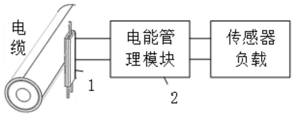
[0026] like figure 1 As shown, the non-closed magnetic core induction power taking device of the present invention includes a linear drawable magnetic core coil assembly 1 and a power management module 2 connected with the linear drawable magnetic core coil assembly 1 . Among them, the linear movable magnetic core coil assembly 1 is clamped to the surface of the cable to be collected, and is set to convert the magnetic energy of the cable to be collected into the output signal of the linear movable magnetic core coil assembly 1; the power management module 2 and the sensor load It is used to convert the output signal of the linear twitchable magnetic core coil assembly 1 into a stable power supply voltage, so as to provide the sensor load.

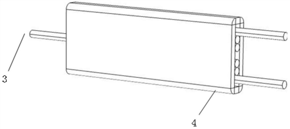
[0027] like figure 2 As shown, the linear drawable magnetic core coil assembly 1 includes a plurality of thi...

Embodiment 2

[0033] Embodiment 2 Non-closed magnetic core induction power take-off device with right-angle twitchable magnetic core coil assembly

[0034] like Figure 4 As shown, the non-closed magnetic core inductive power taking device includes: a right-angle drawable magnetic core coil assembly 5 and a power management module 6 connected to the right-angle drawable magnetic core coil assembly 5 . Among them, the right-angle twitchable magnetic core coil assembly 5 is snap-connected to the surface of the cable to be collected, and is set to convert the magnetic energy of the cable to be collected into the output signal of the right-angle twitchable magnetic core coil assembly 5; the power management module 6 and the sensor load It is connected to convert the output signal of the right-angle twitchable magnetic core coil assembly 5 into a stable power supply voltage, so as to provide the sensor load.

[0035] like Figure 5 As shown, the non-closed right-angle twitch magnetic core coil...


PUM

PropertyMeasurementUnit
diameteraaaaaaaaaa
areaaaaaaaaaaa
heightaaaaaaaaaa

Abstract

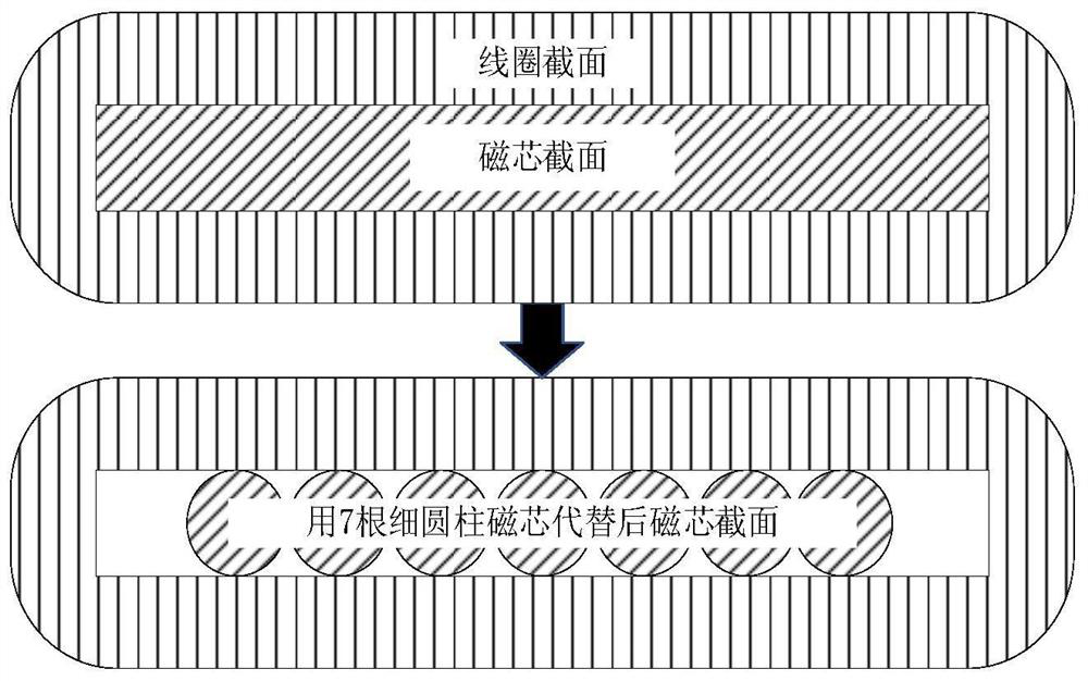
The invention provides an induction power taking device of a non-closed type magnetic core, which comprises a non-closed type drawable magnetic core coil assembly and an electric energy management module connected with the drawable magnetic core coil assembly, and is characterized in that the drawable magnetic core coil assembly comprises a plurality of thin column type magnetic cores and a magnetic core coil arranged on the outer sides of all the thin column type magnetic cores in a sleeving manner; at least a portion of the fine cylindrical core is drawable with respect to the core coil. The non-closed type magnetic core is adopted in the induction power taking device of the non-closed type magnetic core, the problem that different voltage classes of the induction power taking device are matched and compatible with the cable diameter is solved, meanwhile, a traditional whole magnetic core is equivalently replaced by several thin magnetic cores with higher effective magnetic conductivity, the magnetic cores can be drawn to change the length of a magnetic circuit in the magnetic cores, and therefore the magnetic core can be replaced by the thin magnetic cores with higher effective magnetic conductivity. And the output power and the power density of the whole magnetic core can be improved.

Description

technical field [0001] The invention belongs to the technical field of inductive power taking, and more particularly, relates to an inductive power taking device with a non-closed magnetic core. Background technique [0002] At present, with the proposal of the dual carbon goal, the development of a new power system with intelligent sensing capability is a key link, and a large number of wireless sensors are the key to achieving "comprehensive sensing and interconnection". The power supply problem of the power sensor is the core module that restricts its large-scale application. The methods of power supply for online power monitoring sensors mainly include battery power supply, solar power supply, laser power supply, resonant coupling power supply, vibration power supply, capacitive partial voltage power supply, magnetic field induction power supply, etc. Inductive power supply is due to its stability and stability. Maturity is the most widely used. [0003] At present, fo...

Claims


Application Information

Patent Timeline
Patent Type & Authority Applications(China)
IPC IPC(8): H02J50/00H02J50/10H01F27/24H01F27/30H02J7/02
CPCH02J50/005H02J50/10H01F27/24H01F27/306H02J7/02Y02T10/70
Inventor 李伟杨洋甘峰源周易杨雪雷
Owner SHANGHAI INST OF MICROSYSTEM & INFORMATION TECH CHINESE ACAD OF SCI
Learn More