Multi-spindle machining center and system with micro-motion compensation function

A processing center and spindle processing technology, which is applied in the direction of manufacturing tools, comprehensive factory control, and other manufacturing equipment/tools, etc., can solve problems such as difficulty in fine movement, and achieve the effect of small movement range, convenient operation, and reduced operating space

Active Publication Date: 2022-08-09
友嘉国际数控机床有限公司
View PDF9 Cites 0 Cited by
  • Summary
  • Abstract
  • Description
  • Claims
  • Application Information

AI Technical Summary

Problems solved by technology

[0007] In order to overcome the defect that the main shaft of the machining center in the prior art is easy to move in the Z-axis and X-axis directions, but the fine movement in the Y-axis direction is difficult, the present invention provides a method that can add fine movements in the Y-axis direction, thereby overcoming A multi-spindle machining center and system with micro-motion compensation function to ensure machining accuracy due to thermal deformation and other factors

Method used


Image

  • Multi-spindle machining center and system with micro-motion compensation function
  • Multi-spindle machining center and system with micro-motion compensation function
  • Multi-spindle machining center and system with micro-motion compensation function

Examples


Embodiment 1

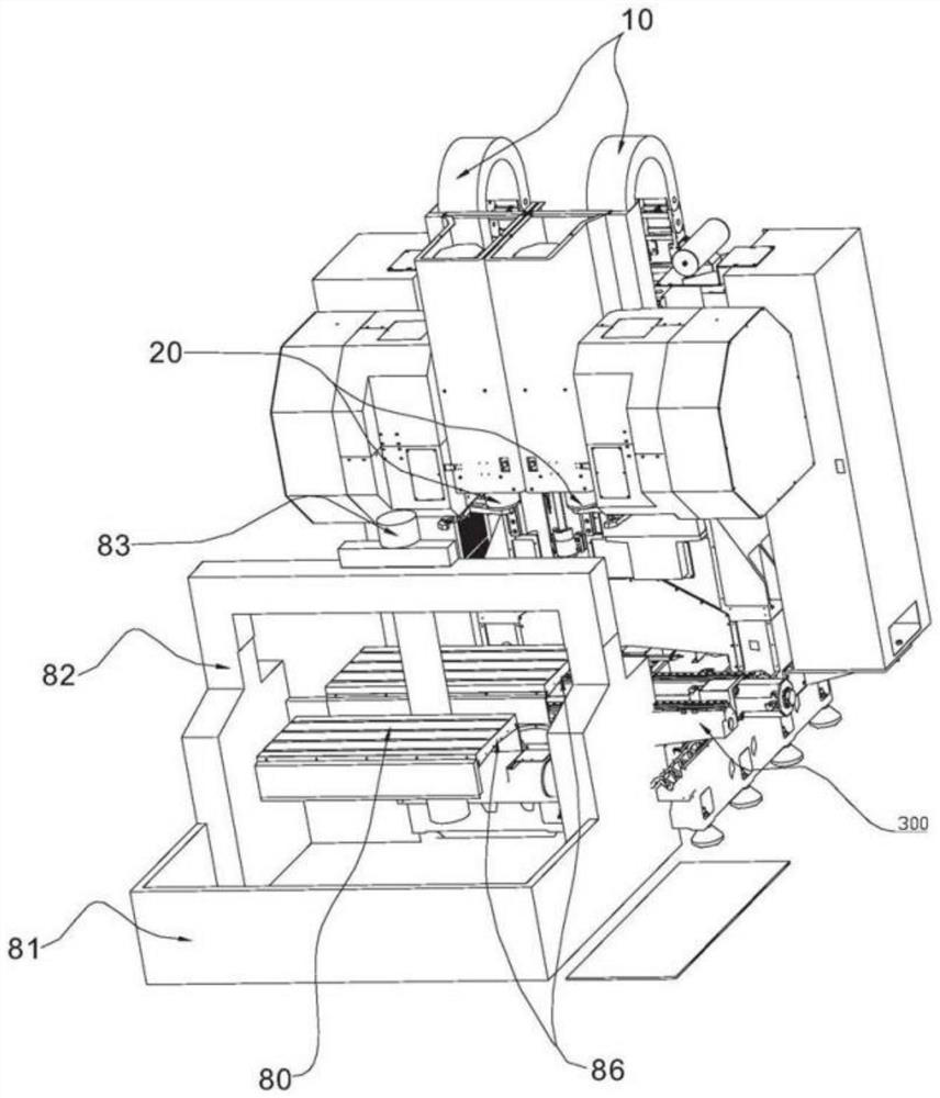
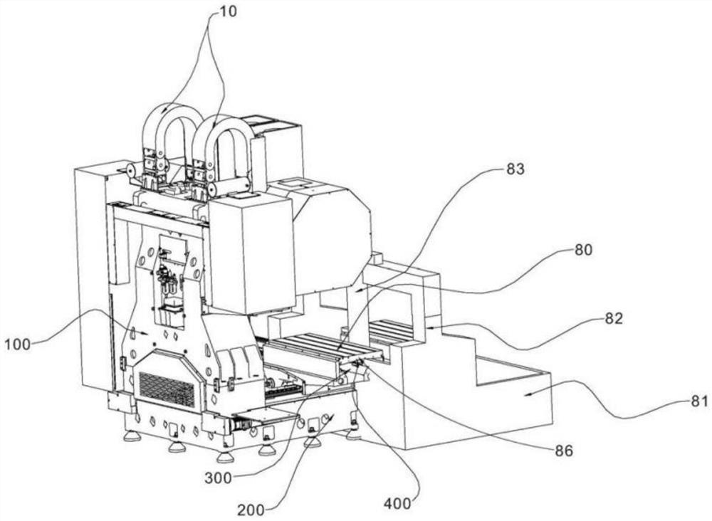
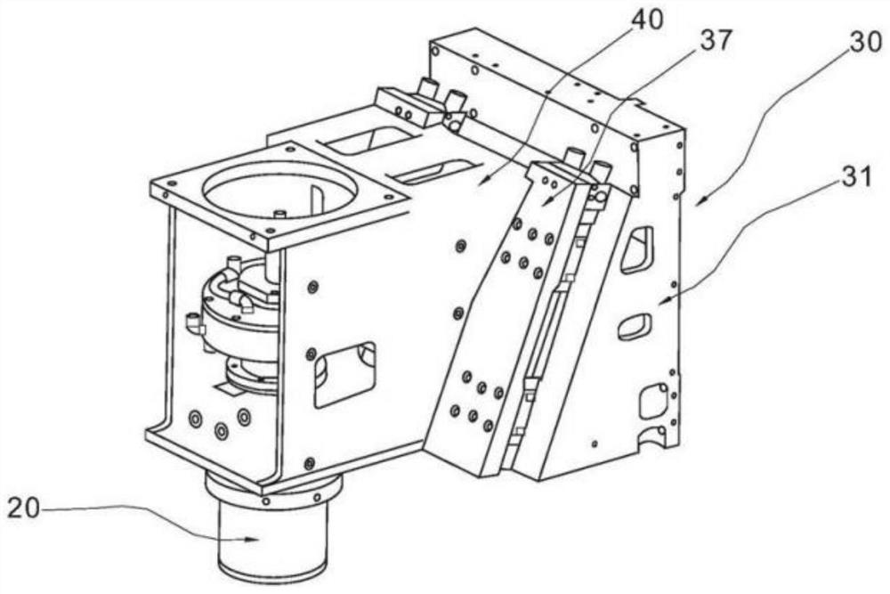
[0047] like Figure 1 to Figure 6 As shown, this embodiment provides a multi-spindle machining center with micro-motion compensation function, including a main base 200, a main column 100, a saddle 300, a worktable 400, two spindle machining units, and a workpiece pallet exchange mechanism. The main column 100 is fixed on the main base 200 and is perpendicular to the ground, the main shaft processing unit is slidably connected to the main column 100, the saddle 300 is slidably connected to the main base 200, and a Y-axis drive mechanism is connected between the saddle 300 and the main base 200 , the worktable 400 is slidably connected to the saddle 300 , and an X-axis drive mechanism is connected between the worktable 400 and the saddle 300 . The spindle machining unit includes a spindle 20 , a micro-motion compensation mechanism 30 and a unit main body 40 . The main shaft 20 is mounted on the unit main body 40 , and a Z-axis driving device 10 is provided between the main shaf...

Embodiment 2

[0050] There are three spindle machining units. The rest are the same as in Example 1.

Embodiment 3

[0052] There are four spindle machining units. The rest are the same as in Example 1.


PUM


Abstract

The multi-spindle machining center with the micro-motion compensation function comprises a main base, a main stand column, a saddle, a workbench and at least two spindle machining units, the main stand column is fixed to the main base, the spindle machining units are connected to the main stand column in a sliding mode, and each spindle machining unit comprises a Z-axis driving device, a spindle and a unit body; the spindle machining unit further comprises a micro-motion compensation mechanism, the micro-motion compensation mechanism comprises a base body, a guide rail and a motor, the guide rail is obliquely arranged on the unit body, the unit body is slidably connected to the guide rail, and a transmission mechanism is connected between the motor and the unit body. According to the invention, fine displacement of each processing point on the workpiece in the Y-axis direction can be subjected to micro-motion compensation, the operation is convenient, and the working efficiency is improved.

Description

[0001] This application is a divisional application for the invention patent titled "A Multi-Spindle Machining Center with Micro-Motion Compensation Function"; the application number of the parent application is: CN202010530104.9; the application date of the parent application is: 2020.06 .11. technical field [0002] The invention relates to a numerical control machining equipment, more particularly, to a multi-spindle machining center and system with micro-motion compensation function. Background technique [0003] The working method of the conventional machining center is that the saddle and the table move in the left and right directions of the X axis and the front and rear directions in the Y axis direction. Move, through the rotating spindle to process the surface, groove, hole and other structures. [0004] In order to improve processing efficiency, some machining center manufacturers have introduced multi-spindle machining centers with multiple spindles that can pro...

Claims


Application Information

Patent Timeline
Patent Type & Authority Applications(China)
IPC IPC(8): B23Q23/00
CPCB23Q23/00Y02P90/02
Inventor 安红卫李彦强廖文杰
Owner 友嘉国际数控机床有限公司
Why Eureka
Try Eureka