Hydraulic turbine set concrete integral pouring method and structure

An integral pouring and concrete technology, applied in building construction, infrastructure engineering, construction, etc., can solve problems such as water leakage, affecting the installation cycle of mechanical and electrical equipment, labor and time-consuming, etc., to achieve smooth water flow, ensure reliability and stability, The effect of enhanced anti-leakage effect

Pending Publication Date: 2022-08-09
新疆银通建设监理有限公司
View PDF0 Cites 0 Cited by
  • Summary
  • Abstract
  • Description
  • Claims
  • Application Information

AI Technical Summary

Problems solved by technology

Reserving basic space for equipment (such as tailwater diffuser pipe, cone section, and elbow section) is labor-intensive and time-consuming, and the installation of electromechanical equipment can only be carried out after the strength of the foundation concrete reaches 70% of the design value, which directly affects the installation period of electromechanical equipment
Before the second phase of concrete pouring, the concrete surface of the first and second phase joints needs to be chiseled. Only the chiseling treatment of the joint surface at this part will cause construction cold joints between the first and second phase concrete joints. May cause water leakage

Method used


Image

  • Hydraulic turbine set concrete integral pouring method and structure
  • Hydraulic turbine set concrete integral pouring method and structure
  • Hydraulic turbine set concrete integral pouring method and structure

Examples


Embodiment Construction

[0025] In order to further illustrate the technical means and effects adopted by the present invention to achieve the predetermined purpose of the invention, the following in conjunction with the accompanying drawings and preferred embodiments, the specific embodiments, structures, features and effects of the application according to the present invention are described in detail as follows . In the following description, different "an embodiment" or "embodiments" do not necessarily refer to the same embodiment. Furthermore, the particular features, structures, or characteristics in one or more embodiments may be combined in any suitable form.

[0026] The present invention will be further described in detail below in conjunction with the accompanying drawings and embodiments.

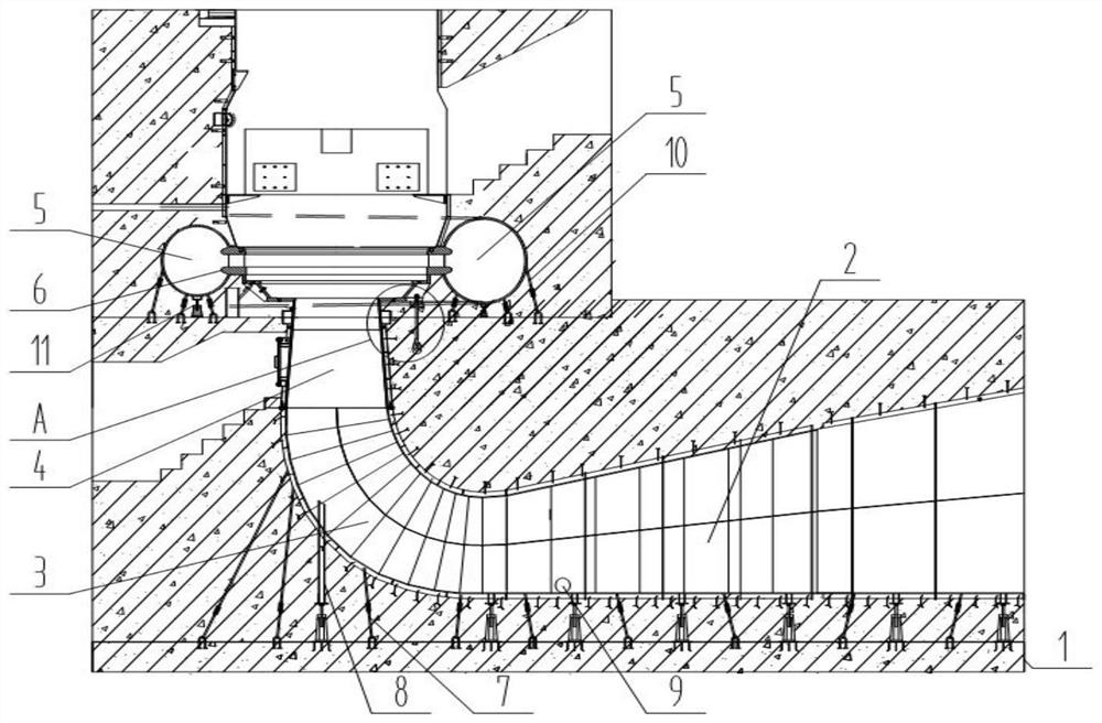
[0027] like figure 1 As shown, on the one hand, an embodiment of the present invention provides an integral concrete pouring method for a hydraulic turbine unit, which includes: step 1, prefabricating...


PUM


Abstract

The invention discloses a hydraulic turbine set concrete integral pouring method and structure, relates to the technical field of hydropower engineering construction, and aims to improve the pouring construction efficiency and construction quality of a hydraulic turbine set structure. According to the main technical scheme, the integral concrete pouring method for the hydraulic turbine set comprises the following steps that firstly, a pull anchor and a steel buttress are prefabricated, and the pull anchor and the steel buttress are pre-buried in foundation slab concrete in advance in the process of pouring the foundation slab concrete; secondly, a tail water diffusion pipe, an elbow pipe and a taper pipe are installed, and after the steel buttress is installed and reinforced, a pull anchor is tensioned; step 3, checking the mounting elevations of the tail water diffusion pipe, the elbow pipe and the taper pipe by using a level gauge, and checking the perpendicularity and levelness of the tail water diffusion pipe, the elbow pipe and the taper pipe by using a frame type gradienter; step 4, using a level gauge to introduce an elevation control point near a pouring part, respectively placing a pair of box staff on the tail water diffusion pipe, the elbow pipe and the taper pipe, and measuring the elevation value of each part before pouring.

Description

technical field [0001] The invention relates to the technical field of hydropower engineering construction, in particular to a concrete integral pouring method and structure for a hydraulic turbine unit. Background technique [0002] For the general concrete construction of power plant units, for the installation of mechanical and electrical equipment, it is often necessary to reserve the second-phase concrete during the main construction process, and then install the mechanical and electrical equipment, and then carry out the second-phase concrete pouring. This type of construction method directly prolongs the overall construction period of the power plant. During concrete construction, the use of formwork materials is large, and the requirements for the first-stage concrete formwork and the second-stage concrete formwork and size are high. Reserving basic space for equipment (such as tailwater diffuser, cone pipe section, elbow pipe section) is labor-intensive and time-con...

Claims


Application Information

Patent Timeline
Patent Type & Authority Applications(China)
IPC IPC(8): E02D15/02E02D27/44E02D31/02E04B1/41E03F3/04
CPCE02D15/02E02D27/44E02D31/02E04B1/41E03F3/04Y02E10/20
Inventor 龙飞邱明路王小刚王吉祥张鹤翟奎耿屹晨
Owner 新疆银通建设监理有限公司
Why Eureka
Try Eureka