
Method for forming surface acoustic wave resonance device

A resonator device, surface acoustic wave technology, applied in impedance networks, electrical components, etc., can solve the problem that the resonator forming process needs to be improved, etc.

Active Publication Date: 2022-08-09
CHANGZHOU CHEMSEMI CO LTD
View PDF3 Cites 1 Cited by
  • Summary
  • Abstract
  • Description
  • Claims
  • Application Information

AI Technical Summary

Problems solved by technology

[0004] However, the existing resonator formation process still needs to be improved

Method used


Image

  • Method for forming surface acoustic wave resonance device
  • Method for forming surface acoustic wave resonance device
  • Method for forming surface acoustic wave resonance device

Examples


Embodiment Construction

[0026] As described in the background art, the existing resonator formation process still needs to be improved, which will be described in detail below with reference to the accompanying drawings.

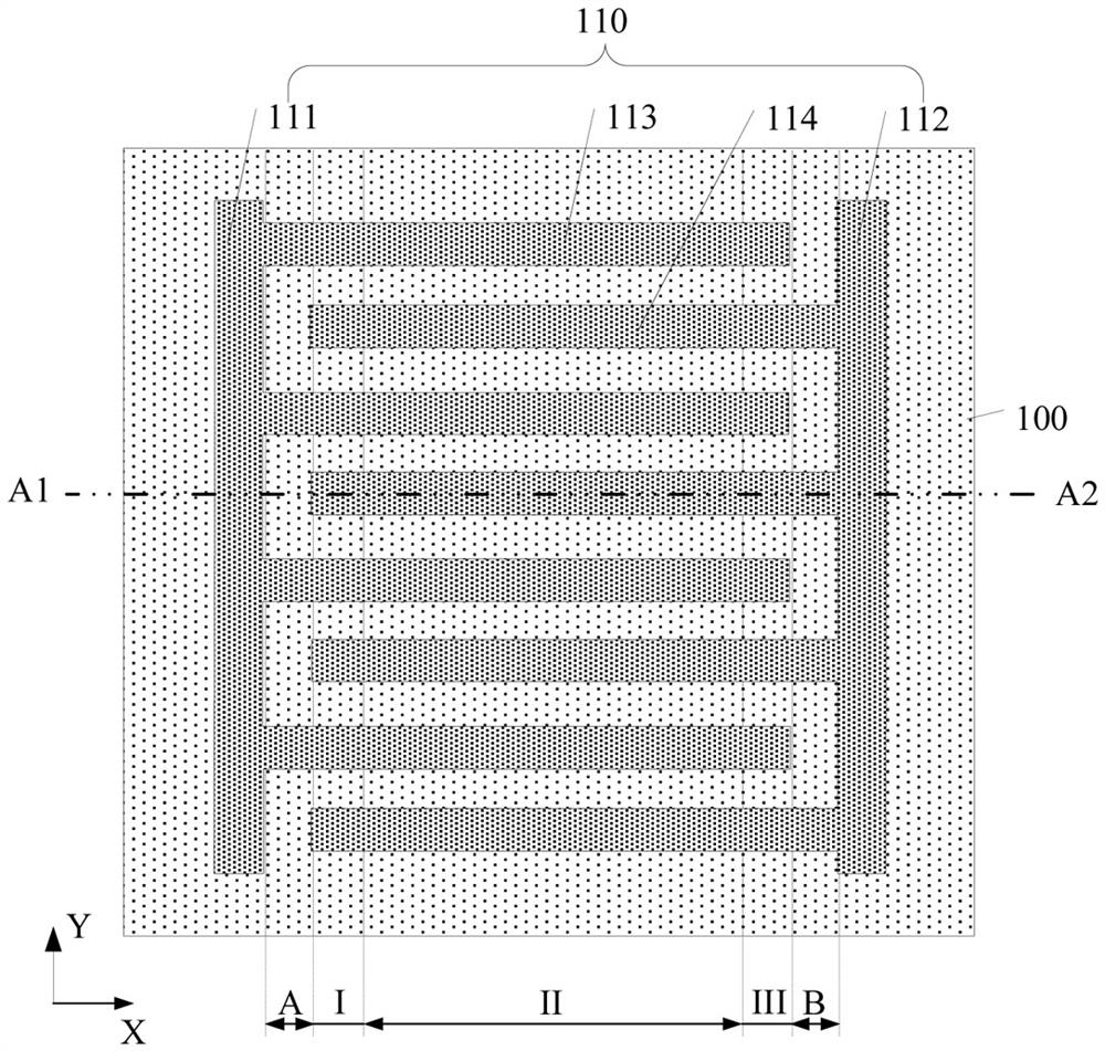
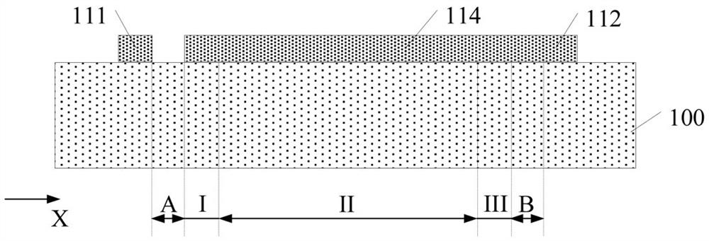
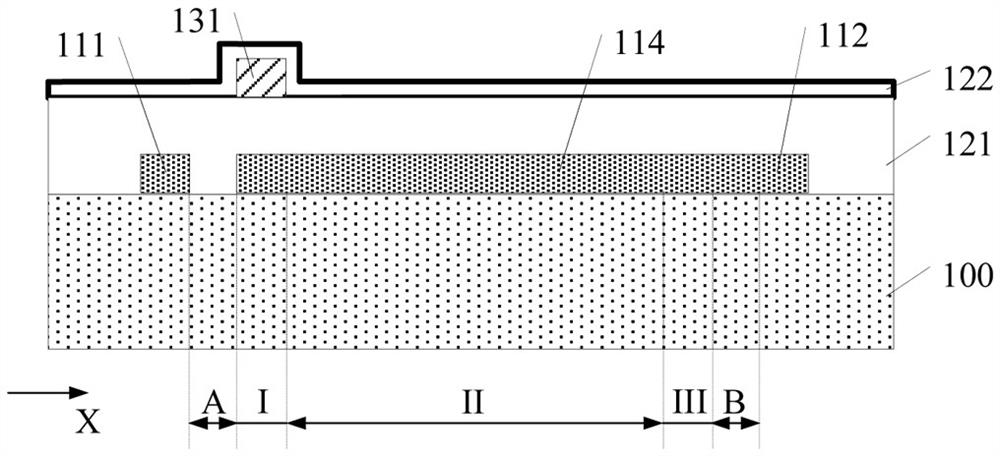
[0027] Figure 1 to Figure 6 It is a structural schematic diagram of each step in the formation process of a SAW resonator.

[0028] Please refer to figure 1 and figure 2 , figure 1 Yes figure 2 Schematic top view of the structure, figure 2 Yes figure 1 A schematic cross-sectional structure diagram along the direction A1-A2 in the middle, a piezoelectric substrate 100 is provided, and the piezoelectric substrate 100 has an electrode layer 110 thereon.

[0029] The piezoelectric substrate 100 includes a first isolation region A, a first region I, a second region II, a third region III and a second isolation region B which are sequentially arranged in the first direction X.

[0030] The electrode layer 110 includes: a first bus line 111 , a second bus line 112 , a plurali...


PUM


Abstract

A method for forming a surface acoustic wave resonance device relates to the technical field of semiconductors, and comprises the following steps: providing a piezoelectric substrate which comprises a first spacer region, a first region, a second region, a third region and a second spacer region which are sequentially arranged along a first direction; forming an electrode layer on the surface of the piezoelectric substrate, wherein the electrode layer comprises a first bus, a second bus, a plurality of first electrode strips connected with the first bus, and a plurality of second electrode strips connected with the second bus; a first temperature compensation layer is formed on the surfaces of the piezoelectric substrate and the electrode layer, the first temperature compensation layer comprises a first compensation area and a second compensation area, and the surface, on the first compensation area, of the first temperature compensation layer is higher than the surface, on the second compensation area, of the first temperature compensation layer; and forming a first load layer located on the first region and a second load layer located on the third region on the surface of the first temperature compensation layer. Therefore, an existing forming process is improved.

Description

technical field [0001] The present invention relates to the technical field of semiconductors, and in particular, to a method for forming a surface acoustic wave resonance device. Background technique [0002] The radio frequency (RF) front-end chip of wireless communication equipment includes: power amplifier (PA), antenna switch, RF filter, multiplexer including duplexer (multiplexer) and low noise amplifier (Low Noise Amplifier, LNA) etc. Among them, the RF filter includes piezoelectric surface acoustic wave (Surface Acoustic Wave, SAW) filter, piezoelectric bulk acoustic wave (Bulk Acoustic Wave, BAW) filter, micro-electromechanical system (MicroElectroMechanical System, MEMS) filter, integrated passive Device (Integrated Passive Devices, IPD) filter and so on. [0003] The Q value of the SAW resonator is high. Therefore, the RF filter (ie SAW filter) made based on the SAW resonator has low insertion loss (insertion loss) and high outofband rejection (outofband rejecti...

Claims


Application Information

Patent Timeline
IPC IPC(8): H03H3/08H03H3/10H03H9/02H03H9/25
CPCH03H3/08H03H3/10H03H9/02834H03H9/02818H03H9/25
Inventor 韩兴周建邹雅丽王斌
Owner CHANGZHOU CHEMSEMI CO LTD
Learn More