Method and equipment for radiating ion beam, related method and its equipment

A technology of ion beam and irradiation, applied in the field of ion beam irradiation, to achieve the effect of reducing charging voltage, reducing charging and increasing production

Inactive Publication Date: 2004-10-20
NISSIN ION EQUIP CO LTD
View PDF0 Cites 1 Cited by
  • Summary
  • Abstract
  • Description
  • Claims
  • Application Information

AI Technical Summary

Problems solved by technology

This is difficult to accomplish with existing techniques as described earlier

Method used


Image

  • Method and equipment for radiating ion beam, related method and its equipment
  • Method and equipment for radiating ion beam, related method and its equipment
  • Method and equipment for radiating ion beam, related method and its equipment

Examples


Embodiment Construction

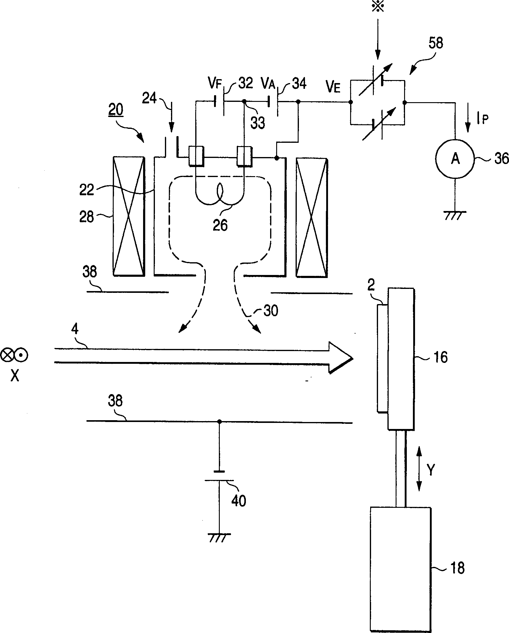
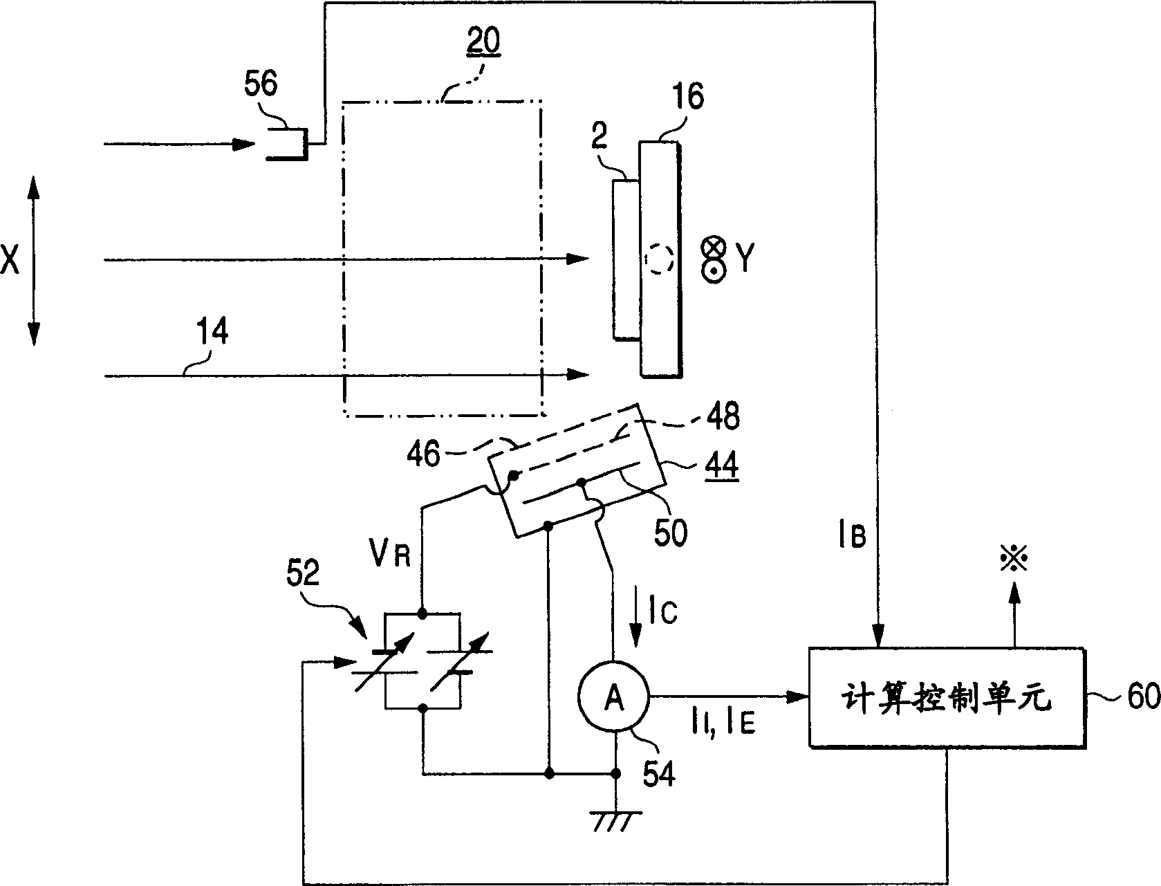
[0042] figure 1 It is a side view showing an example of an ion beam irradiation device used to perform the ion beam irradiation method of the present invention. figure 2 Is a plan view, it shows figure 1 Around the substrate of the device shown. In the display of conventional examples figure 1 with figure 2 with Figure 6 In the schematic diagrams, similar reference characters are used to indicate similar components. Only the difference from the conventional example is explained as follows.

[0043] First, refer to figure 1 In the ion beam irradiation device, the ammeter 36 is connected between the plasma generating container 22 of the plasma generating device 20 and the ground through the DC traction power supply 58. The strength and polarity of the output voltage of the traction power supply 58 can be obtained. Therefore, it is possible to use the traction power source 58 to apply a positive and negative traction voltage V to the plasma generating container 22 E .

[0044...


PUM


Abstract

When ion beam 14 is irradiated onto a substrate 2 to conduct processing such as ion injection, plasma 30 emitted from a plasma generating device 20 is supplied to a portion close to the substrate 2 to suppress electric charging on a substrate surface caused by ion beam irradiation. A ratio of IE / IB is kept at a value not lower than 1.8, a ratio of II / IE is kept at a value not lower than 0.07 and not higher than 0.7, wherein IB is an electric current of the ion beam 14 irradiated onto the substrate 2, II is an ion current expressing a quantity of ions in the plasma 30 emitted from the plasma generating device 20, and IE is an electron current expressing a quantity of electrons in the plasma 30.

Description

Technical field [0001] The present invention relates to a method and apparatus for irradiating an ion beam, which is used to irradiate a substrate for processing such as ion implantation. The present invention also relates to a method of manufacturing a semiconductor device by irradiating a semiconductor substrate with an ion beam. More specifically, the present invention relates to an apparatus for suppressing charge-up that occurs during ion beam irradiation. Background technique [0002] Figure 6 It is a side view, which shows an example of conventional ion beam irradiation. For the relationship between substrate 2 and ion beam 14, please refer to figure 2 Floor plan. [0003] The ion beam irradiation device can perform processing such as ion implantation, which is specifically described as follows. The point-shaped ion beam drawn from the ion source (not shown) is mass-separated and accelerated, and then irradiated on the substrate 2 (for example, a semiconductor substrate...

Claims


Application Information

Patent Timeline
Patent Type & Authority Patents(China)
IPC IPC(8): C23C14/48C23C14/00C23C16/00C30B31/22H01J37/02H01J37/04H01J37/20H01J37/317H01L21/223H01L21/265H01L21/42H01L21/66
CPCH01J2237/004H01J37/026H01J2237/31701H01L21/2236H01L21/265
Inventor 酒井滋树池尻忠司
Owner NISSIN ION EQUIP CO LTD
Why Eureka
Try Eureka