Astigmatism eliminating three spherical reflector system

A spherical mirror, astigmatism elimination technology, applied in the field of optical systems, can solve the problems of difficult processing and adjustment, high development cost, difficult mass production, etc. Difficulty reduction effect

Inactive Publication Date: 2004-10-27
TSINGHUA UNIV
View PDF3 Cites 0 Cited by
  • Summary
  • Abstract
  • Description
  • Claims
  • Application Information

AI Technical Summary

Problems solved by technology

Although the three-reflection system can achieve a compact structure, a larger field of view, and a structure that is conducive to eliminating stray light, but after all, because of the complexity of processing and adjustment brought by its three aspherical surfaces and the high development cost largely restricted
In the Chinese patent with the publication number CN1350190A published on May 22, 2002, an improved three-reflection astigmatism elimination system is proposed, and one of the three aspheric mirrors in the three-reflection system is designed as a spherical surface mirror, while the other two mirrors retain the secondary aspheric surface, but the processing and assembly of the two aspheric mirrors are still very difficult. Therefore, the development cost of the long focal length optical system remains high and it is difficult to carry out mass production

Method used


Image

  • Astigmatism eliminating three spherical reflector system
  • Astigmatism eliminating three spherical reflector system
  • Astigmatism eliminating three spherical reflector system

Examples


Embodiment 1

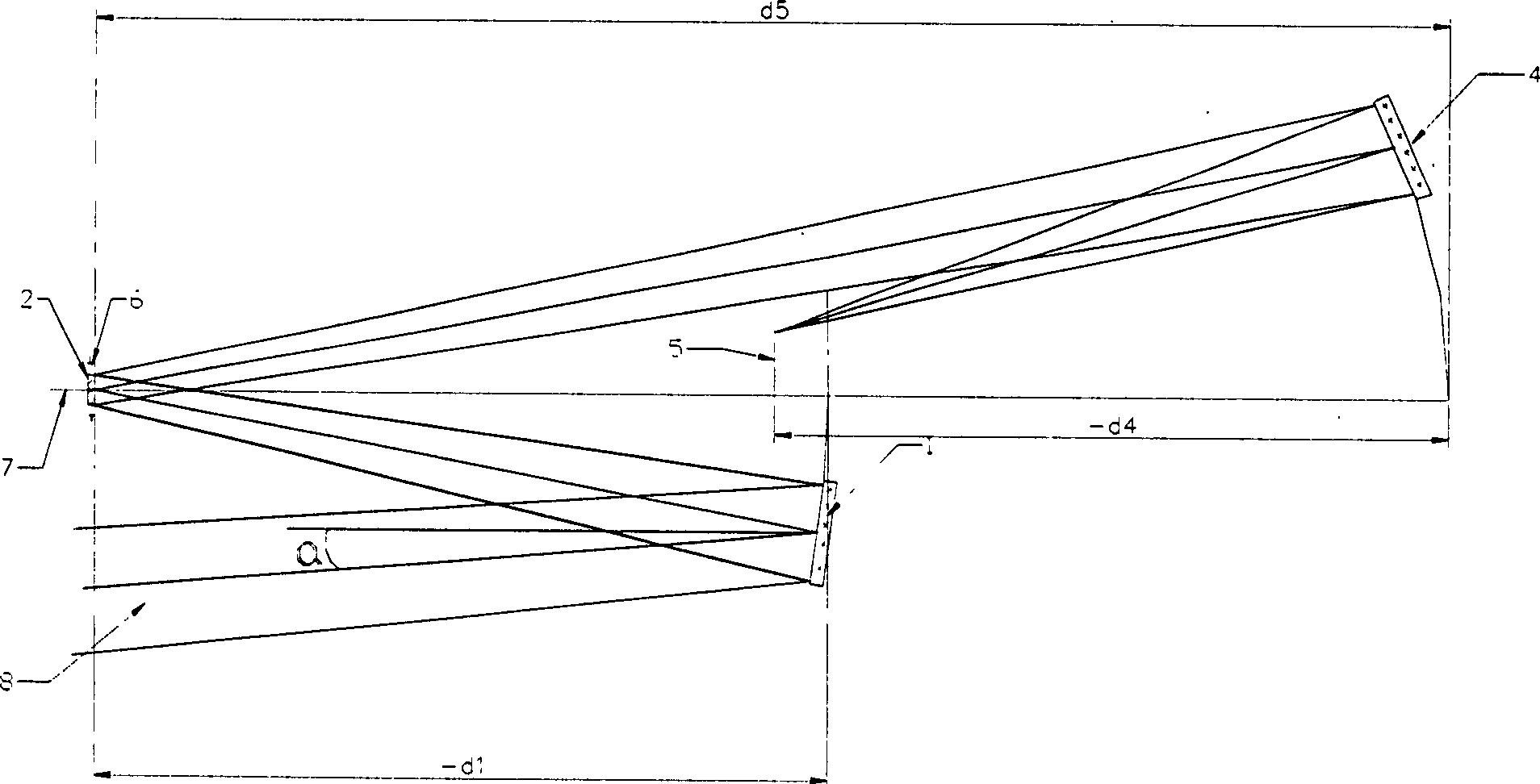
[0027] Embodiment 1 is an aerospace push-broom imaging optical system, and its structure is as follows: figure 1 Shown by:

[0028] Focal length f'=800mm; field of view is 3°×0.5°; relative aperture is 1 / 12;

[0029] Dimensions: (1300×400×150)mm 3 ; Spectral segment: (0.5-0.78) micron;

[0030] System working field of view: X direction is (-1.5° to 1.5°); Y direction is (3.5° to 4.0°).

[0031] Structural parameters of the primary mirror 1: the radius of curvature is -2431.698mm (concave); the distance d1 between the primary and secondary mirrors is -700mm; the Y off-axis distance is -109.437mm; the tilt is 0; the eccentricity coefficient is 0; the clear aperture is (55.29×41.18)mm 2 .

[0032] Structural parameters of secondary mirror 2: radius of curvature is -743.898mm (convex); distance d5 from secondary mirror to third mirror is 1299.759mm; Y off-axis value is 0; tilt value is 0; eccentricity coefficient is 0; clear aperture diameter It is 14.1mm.

[0033] The stru...

Embodiment 2

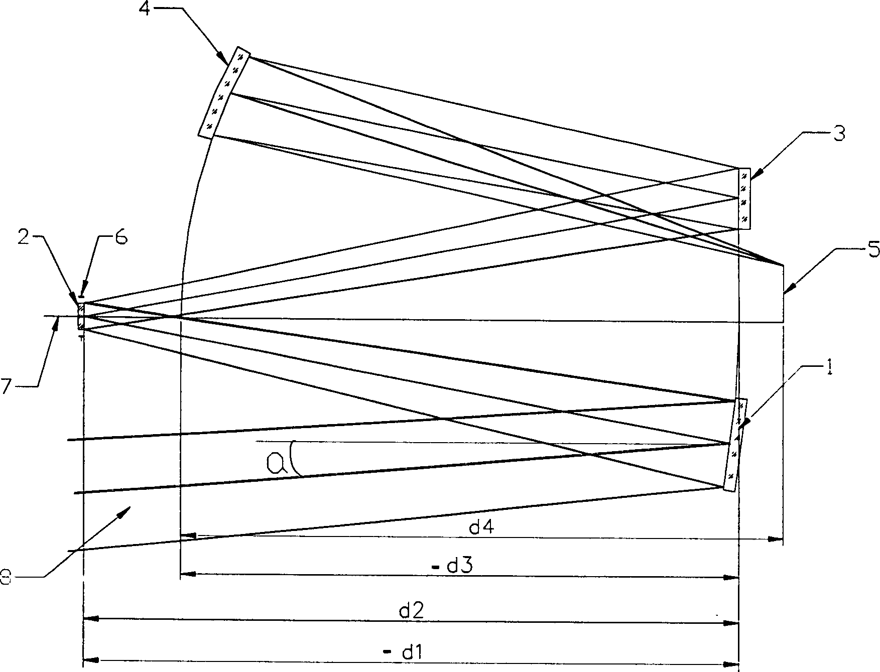
[0037] Embodiment 2 is a push-broom optical system for a microsatellite or a reconnaissance aircraft, and its structure is as follows: figure 2 Shown:

[0038] Focal length f'=500mm; field of view is 6°×0.8°; relative aperture is 1 / 12;

[0039] Dimensions: (482×440×260)mm 3 ; Spectral segment: (0.5-0.78) micron;

[0040] Offset field of view: (-3° to 3°) in the X direction; (4.2° to 5.0°) in the Y direction.

[0041] Structural parameters of primary mirror 1: radius of curvature is -1519.828mm (concave surface); distance d1 between primary mirror 1 and secondary mirror 2 is -437.5mm; Y off-axis is -84.692mm; inclination is 0; eccentricity coefficient is 0 ; Clear aperture is (77×30)mm 2 .

[0042] The structural parameters of the secondary mirror 2: the radius of curvature is -464.944mm (convex); the distance d2 between the secondary mirror 2 and the folding mirror 3 is 437.5mm; the Y off-axis is 0mm; the inclination is 0; the eccentricity coefficient is 0; The light ap...


PUM


Abstract

The astigmatism eliminating three-spherical reflector system provides by the present invention aims at facilitating the machining and regulation of reflective optical system and reducing its development cost. The astigmatism eliminating three-spherical reflector system includes three, primary, secondary and the third, spherical reflectors with one common optical axis. The system has abaxial working field of view. The parallel light beam incident to the primary reflector is thrice reflected in the primary reflector, secondary reflector and the third reflector successively to image in the image plane. The said optical surfaces of the reflectors are spherical with the common optical axis, so the system is easy-to-make and-regulate, low in cost and suitable for mass production.

Description

technical field [0001] The invention belongs to the field of optical systems, in particular to a reflective optical imaging system. Background technique [0002] Reflective astigmatism-eliminating optical systems are generally designed with the help of aspheric surfaces. In recent years, as the aspheric surface manufacturing process and assembly process have become increasingly mature, they have been more and more widely used, especially long-focus reflective astigmatism-eliminating optical systems. It is more common in aerospace applications. Generally, the three-reflection astigmatism elimination system is a type that has been studied more. For example, the three-reflection astigmatism elimination system mentioned in U.S. Patent No. 4,131,485, published on December 26, 1978, uses three The sub-aspherical design has 7 independent variables when the focal length is determined, which can better arrange the aberration and external dimensions. Sometimes, in order to expand the...

Claims


Application Information

Patent Timeline
Patent Type & Authority Patents(China)
IPC IPC(8): G02B5/10G02B17/06
Inventor 郝云彩尤政
Owner TSINGHUA UNIV
Why Eureka
Try Eureka