

Unbounded ejector for conveying condensed oil and its conveying method
An ejector, heavy oil technology, applied in the direction of jet pump, jet device, liquid jet device, etc., to achieve uniform pressure, improve delivery efficiency, and reduce energy consumption
- Summary
- Abstract
- Description
- Claims
- Application Information
AI Technical Summary
Problems solved by technology
Method used
Image

Examples
Embodiment 1
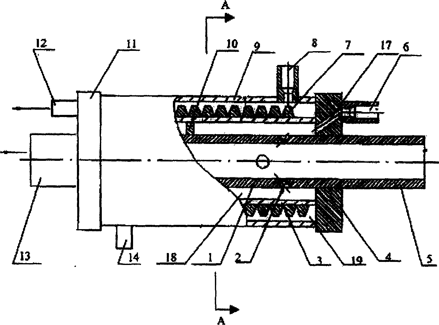
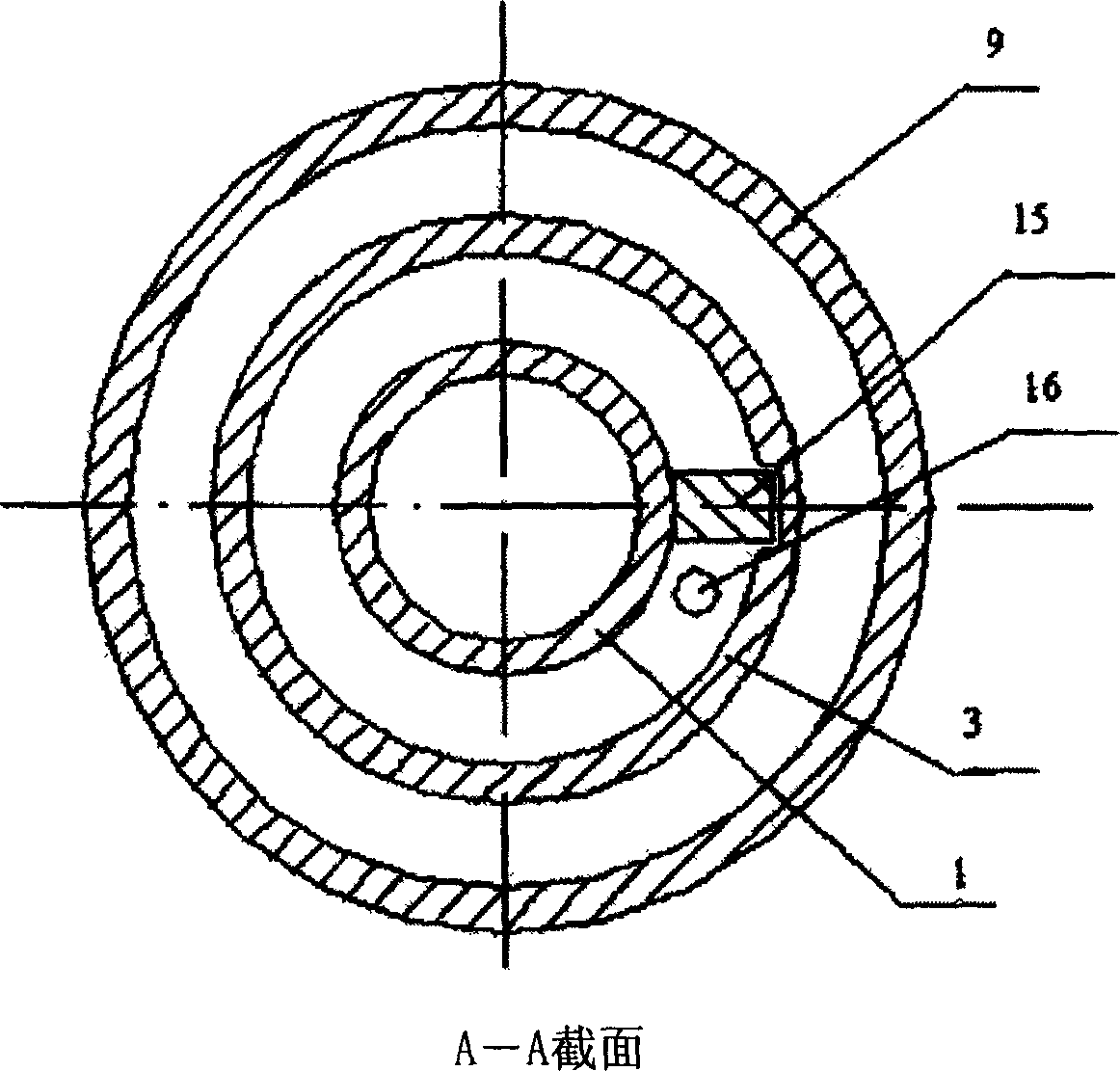
[0030] according to figure 1Make a steam ejector for unbounded ejection in long-distance heavy oil transportation pipelines in oil fields, using high-quality steel to make a cylindrical nozzle seat 1 with an inner diameter of 80mm×length 600mm, and a cylindrical nozzle seat 1 with an inner diameter of 136mm×length 300mm 3 high-quality steel cylinder-shaped insulation seats are covered outside the nozzle seat 1, and an inner diameter is that 171mm * long 300mm high-quality steel overcoat 9 covers are made into the mixing section of the ejector outside the insulation seat 3. One end of the mixing section is connected with the sealing gasket and the bottom end cover 11 through threads, and the other end is integrated with the sealing gasket and the flange 4 through screws; there is a round hole in the center of the bottom end cover 11 with an inner diameter of 136mm, and the inner diameter of the round hole is the same as the nozzle The inner diameter of the seat 1, the inner dia...
Embodiment 2
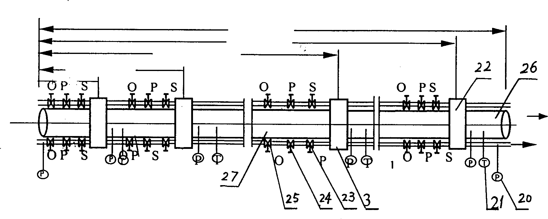
[0032] First press the principle (claim 1) of delivery method of the present invention, made the injector 22 of embodiment 1, press image 3 4 ejectors 22 of the present invention are installed on the oil pipeline 26 of 300 meters, and two ejectors 22 are installed in the range of 20 meters away from the oil pipeline 26 entrances, so that the heavy oil is heated rapidly in a short distance; The third ejector 22 is installed at a position of about 1 meter, and its effect is to be used to make up for the heat loss caused by the heat dissipation of the pipe wall; Remove the residual oil in the pipeline when the pipeline is started or shut down.
[0033] After the pipeline is installed, open the opening valve 25 on the steam pipeline 27, and adjust the pressure regulating valve 23 in consideration of the pressure drop on the steam pipeline, so that the gauge pressure of the steam pressure gauge 20 is 0.2MPa, and the pressure is measured by the pressure gauge 20, 10 A pressure gau...
PUM
 Abstract
Description
Claims
Application Information