Heterojunction field effect transistor
A heterojunction field effect, transistor technology, applied in transistors, semiconductor devices, electrical components, etc., can solve the problems of reduced current magnification, short life, and deterioration of transistor characteristics.
- Summary
- Abstract
- Description
- Claims
- Application Information
AI Technical Summary
Problems solved by technology
Method used
Image
Examples
no. 1 Embodiment
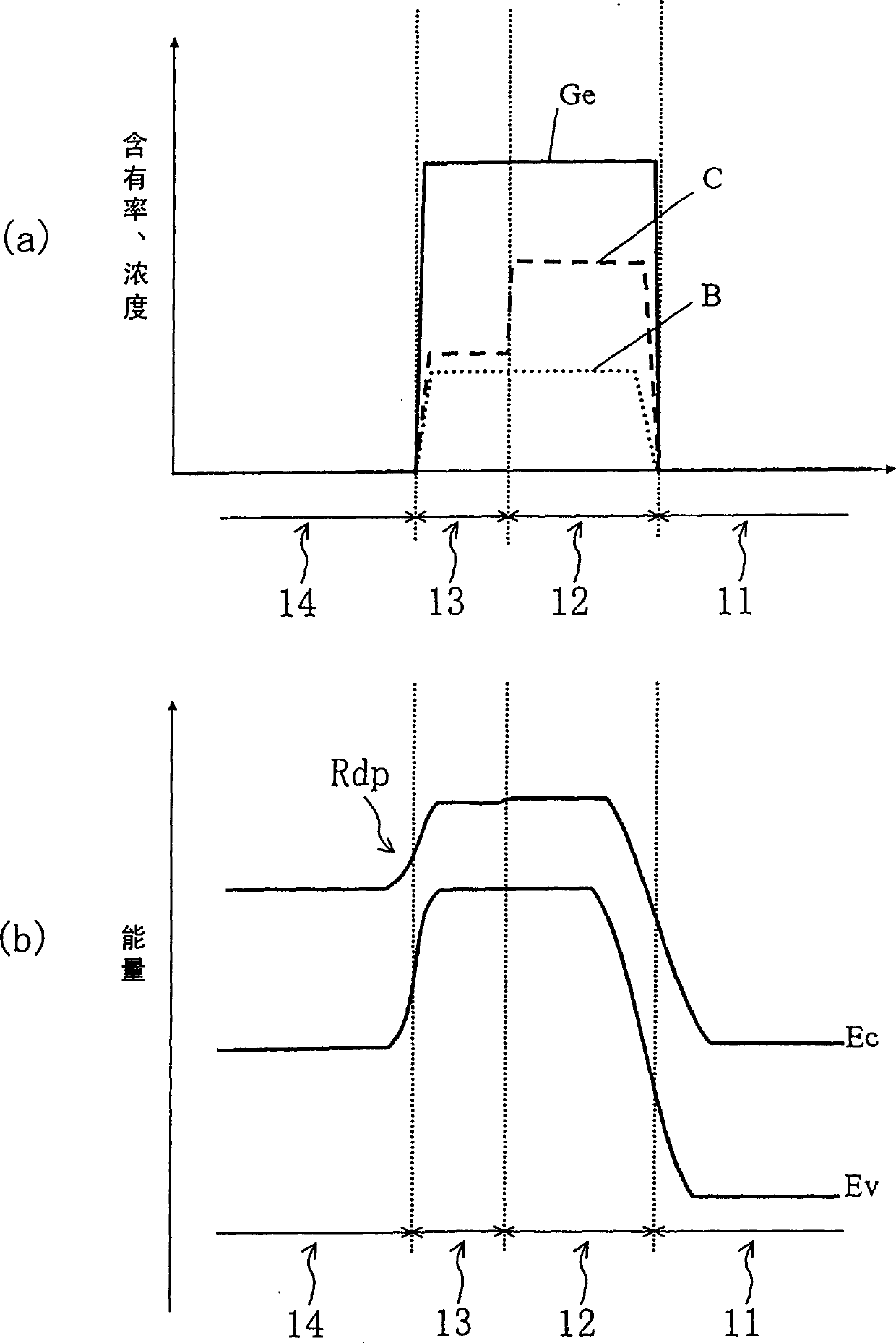
[0060] 3(a) and (b) show the C and Ge contents of the first base region and the second base region and the concentration of impurity boron (B) in the first embodiment, and the emitter region when a voltage is applied. - Energy band diagram of base region-collector region. In addition, illustration of the concentration of n-type impurities is omitted in FIG. 3( a ).
[0061] As shown in FIG. 3( a ), in this embodiment, the Ge content rate is set to a constant value (for example, 26.8%) throughout the first base region 12 and the second base region 13 . On the other hand, the content of C was 0.91% in the first base region 12 and 0.35% in the second base region 13 . That is, the first base region 12 is made of SiGe 0.268 C 0.0091 layers, the second base region 13 is made of SiGe 0.268 C 0.0035 layer composition.
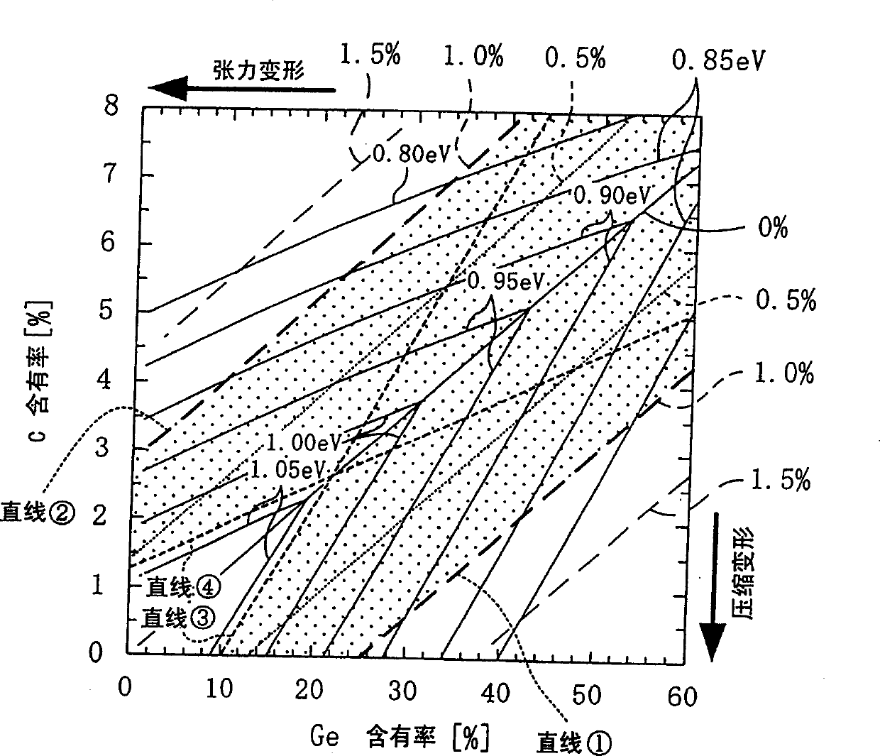
[0062] At this time, SiGe 0.268 C 0.0091 The bandgap of the layer is about 0.95eV, SiGe 0.268 C 0.0035 The bandgap of the layer is about 0.92eV. Therefore, ...
no. 2 Embodiment
[0068] 4(a) and (b) show the C and Ge contents of the first base region and the second base region and the concentration of impurity boron (B) in the second embodiment, and the emitter region when a voltage is applied. - Energy band diagram of base region-collector region. In addition, illustration of the concentration of n-type impurities is omitted in FIG. 4( a ).
[0069] The present embodiment is characterized in that the band gaps of the two regions 12 and 13 are made equal by adjusting the Ge and C contents in the first base region 12 and the second base region 13 . Therefore, the Ge content rate is not set to the same value in the first and second base regions, but the Ge content rate in the first base region 12 is set higher than the Ge content rate in the second base region 13 That's it. When the composition in the SiGeC layer is represented by the general formula Si 1-x-y Ge x C y When the difference in the C content of the first base region 12 and the second ba...
no. 3 Embodiment
[0076] 5(a) and (b) show the C and Ge contents of the first base region and the second base region and the concentration of impurity boron (B) in the third embodiment, and the emitter region when a voltage is applied. Energy band diagram of a base region and a collector region. In addition, illustration of the concentration of n-type impurities is omitted in FIG. 5( a ).
[0077] In this embodiment, it is characterized in that by adjusting the content ratios of Ge and C in the first base region 12 and the second base region 13, the boundary between the first base region 12 and the second base region 13 is made The band gaps of the two are equal, so that the band gap of the first base region 12 changes toward the direction of accelerating base transition electrons. For this reason, when the composition in the SiGeC layer is represented by the general formula Si 1-x-y Ge x C y Indicates that when the difference in C content between the end of the first base region 12 on the ...
PUM
 Abstract
Description
Claims
Application Information
 - R&D
- Intellectual Property
- Life Sciences
- Materials
- Tech Scout
- Unparalleled Data Quality
- Higher Quality Content
- 60% Fewer Hallucinations
Browse by: Latest US Patents, China's latest patents, Technical Efficacy Thesaurus, Application Domain, Technology Topic, Popular Technical Reports.
© 2025 PatSnap. All rights reserved.Legal|Privacy policy|Modern Slavery Act Transparency Statement|Sitemap|About US| Contact US: help@patsnap.com


