
Active high-pass wave filter amplification circuit

A high-pass filter and amplifying circuit technology, used in differential amplifiers, DC-coupled DC amplifiers, multi-terminal pair networks, etc., can solve the problems of cut-off frequency error, low cut-off frequency, poor resistance and capacitance accuracy, etc. range, the effect of improving high frequency characteristics

Inactive Publication Date: 2011-03-30
曾立帅
View PDF0 Cites 7 Cited by
  • Summary
  • Abstract
  • Description
  • Claims
  • Application Information

AI Technical Summary

Problems solved by technology

The resistance value of the existing high-pass filter and the capacitance value of the capacitor have poor accuracy, so that the cut-off frequency determined by their product produces an error
In addition, since the resistance value of the resistor and the capacitance value of the capacitor cannot be made too large, it is difficult to make a circuit with a low cut-off frequency

Method used


Image

  • Active high-pass wave filter amplification circuit
  • Active high-pass wave filter amplification circuit

Examples


Embodiment Construction

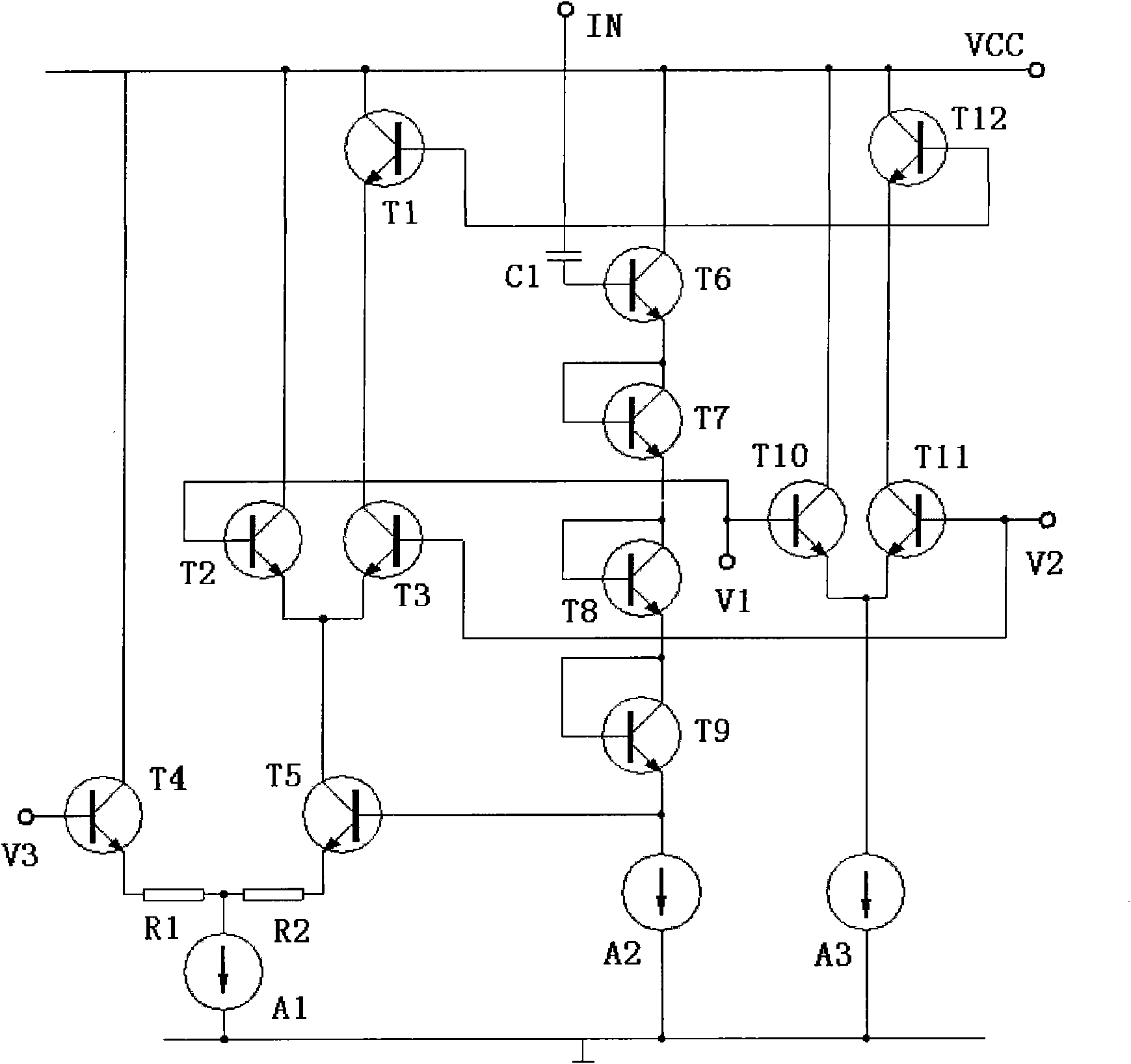
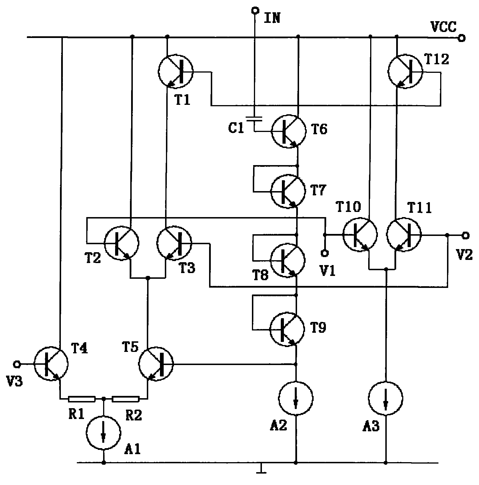
[0008] The circuit of the present invention includes triodes T1, T2, T3, T4, T5, T6, T7, T8, T9, T10, T11, T12, current sources A1, A2, A3, resistors R1, R2, capacitor C1, the first 3. The fourth triode T4 and T5 form a differential amplifier, and the emitters are connected through the first resistor R1 and the second resistor R2, and the node of the first resistor R1 and the second resistor R2 is grounded through the first current source A1 ; The collector of the fourth transistor T4 is connected to the power supply VCC, and the collector of the fifth transistor T5 is connected to the common emitter end of the differential amplifier composed of the second and third transistors T2 and T3. ; The base of the second triode T2 is connected with the base of the thirteenth transistor T10, and the collector is connected with the power supply VCC;

[0009] The base of the third triode T3 is connected to the base of the eleventh triode T11, and the collector is respectively connected t...


PUM


Abstract

The invention discloses an active high-pass wave filter amplification circuit, which relates to an amplification circuit, in particular to an improved structure of the active high-pass wave filter amplification circuit. The invention provides the active high-pass wave filter amplification circuit with good high-frequency characteristic. The active high-pass wave filter amplification circuit comprises a triode, a current source, a resistor and a capacitor.

Description

Technical field: [0001] The present invention relates to an amplifying circuit, more specifically, relates to an improvement of the structure of an active high-pass filter amplifying circuit. Background technique: [0002] The filter composed of RC components and operational amplifiers is called an RC active filter. Its function is to pass signals within a certain frequency range and suppress or sharply attenuate signals outside this frequency range. It can be used in information processing, data transmission, interference suppression, etc., but due to the limitation of the frequency band of the operational amplifier, this type of filter is mainly used in the low frequency range. It is difficult to realize a filter with ideal amplitude-frequency characteristics, and the actual amplitude-frequency characteristics can only be used to approach the ideal. Generally speaking, the better the amplitude-frequency characteristics of a filter, the worse its phase-frequency characteri...

Claims


Application Information

Patent Timeline
Patent Type & Authority Applications(China)
IPC IPC(8): H03H11/12H03F3/45
Inventor 曾立帅
Owner 曾立帅
Learn More