Motor controller
A control device and motor technology, applied in motor control, motor generator control, AC motor control, etc., can solve the d, q axis DC component current control, cannot separate AC component current and DC component current, and control performance. and other problems to achieve the effect of rapid control
- Summary
- Abstract
- Description
- Claims
- Application Information
AI Technical Summary
Problems solved by technology
Method used
Image
Examples
Embodiment 1
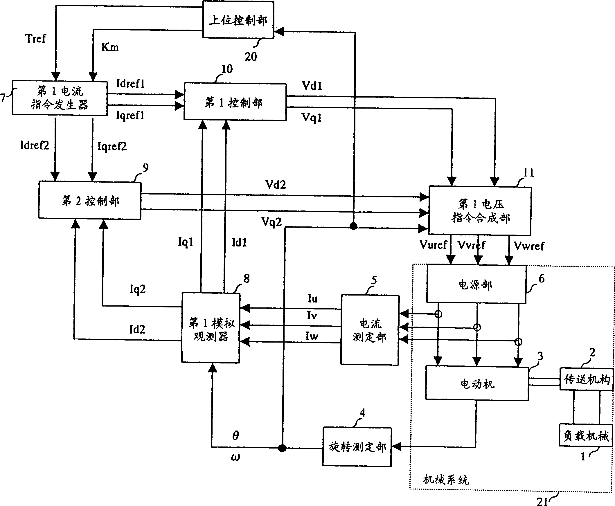
[0153] Below, while referring to figure 1 Next, Embodiment 1 of the present invention will be described.
[0154] figure 1 The illustrated embodiment 1 consists of the following parts:
[0155] It has a load machine 1, a transmission mechanism 2 that transmits power, a motor 3 that drives the load machine 1 through the transmission mechanism 2, and supplies drive according to a U-phase voltage command Vuref, a V-phase voltage command Vvref, and a W-phase voltage command Vwref. The mechanical system 21 of the power supply part 6 of the electric motor 3;
[0156] Provide a rotation measurement unit 4 that observes the state quantity of the mechanical system 21 and provides an actual response signal θ;
[0157] Observing the state quantities of the power supply unit 6, and providing the current measuring unit 5 for the actual U-phase current Iu, the actual V-phase current Iv and the actual W-phase current Iw;
[0158] A host control unit 20 that provides the torque command Tr...
Embodiment 2
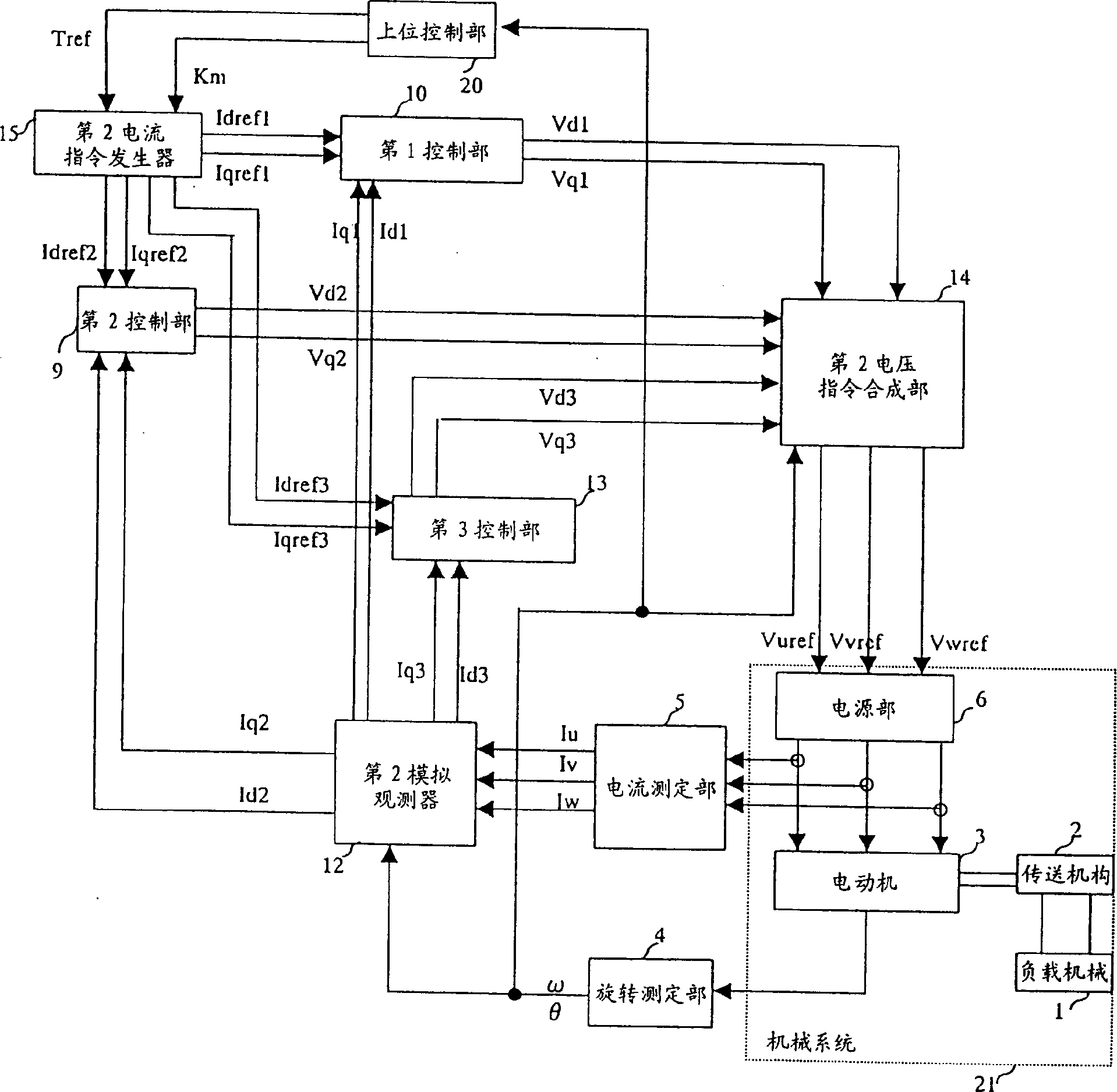
[0204] Below, refer to figure 2 Embodiment 2 of the present invention will be described.
[0205] figure 2 The illustrated embodiment 2 is composed of the following parts:
[0206] Observing the state quantity of the mechanical system 21 and providing the rotation measurement unit 4 with the actual response signal θ;
[0207] Observing the state quantities of the power supply unit 6, and providing the current measurement unit 5 with actual U-phase current Iu, actual V-phase current Iv and actual W-phase current Iw;
[0208] The host control unit 20 that provides the torque command Tref and the control mode command Km;
[0209] According to the torque command Tref and the control mode command Km, the 1d axis current command Idref, the 1q axis current command Iqref1, the 2d axis current command Idref2, the 2q axis current command Iqref2, the 3d axis current command Idref3 and the 3 The second current command generator 15 of the q-axis current command Iqref3;
[0210] Acco...
Embodiment 3
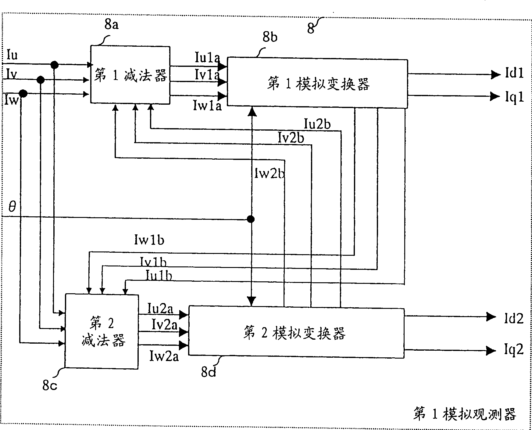
[0263] Below, refer to image 3 Embodiment 3 of the present invention will be described.
[0264] exist image 3 Among them, the first analog observer 8 of Embodiment 3 of the present invention is made up of the following parts:
[0265] Based on the actual U-phase current Iu, the actual V-phase current Iv, the actual W-phase current Iw, the U-phase 2b analog current Iu2b, the V-phase 2b analog current Iv2b, and the W-phase 2b analog current Iw2b, providing The first subtractor 8a of the U-phase 1a analog current Iu1a, the V-phase 1a analog current Iv1a and the W-phase 1a analog current Iw1a;
[0266] Based on the actual U-phase current Iu, the actual V-phase current Iv, the actual W-phase current Iw, the U-phase 1b-th analog current Iu1b, the V-phase 1b-th analog current Iv1b, and the W-phase 1b-th analog current Iw1b, providing The second subtractor 8c of the U-phase 2a analog current Iu2a, the V-phase 2a analog current Iv2a and the W-phase 2a analog current Iw2a;
[026...
PUM
 Abstract
Description
Claims
Application Information
 - R&D
- Intellectual Property
- Life Sciences
- Materials
- Tech Scout
- Unparalleled Data Quality
- Higher Quality Content
- 60% Fewer Hallucinations
Browse by: Latest US Patents, China's latest patents, Technical Efficacy Thesaurus, Application Domain, Technology Topic, Popular Technical Reports.
© 2025 PatSnap. All rights reserved.Legal|Privacy policy|Modern Slavery Act Transparency Statement|Sitemap|About US| Contact US: help@patsnap.com


