Ultra-high strength cryogenic weldments
A technology of welding parts and welding process, applied in the field of ultra-high-strength welding parts, which can solve problems such as unsuitable alloy steel
- Summary
- Abstract
- Description
- Claims
- Application Information
AI Technical Summary
Problems solved by technology
Method used
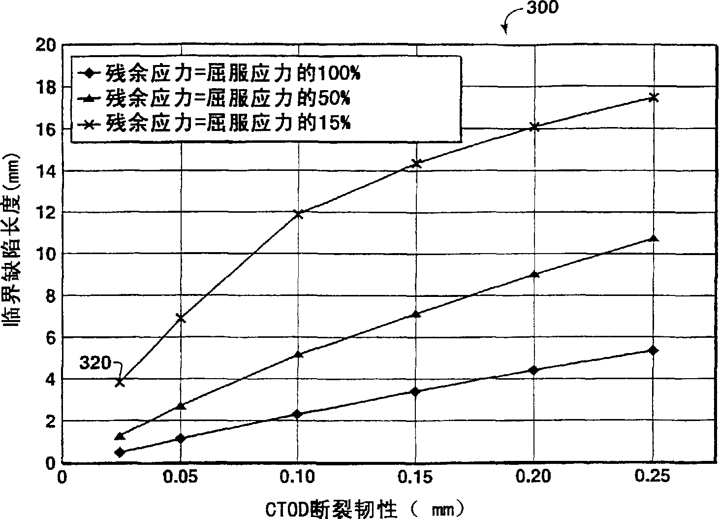
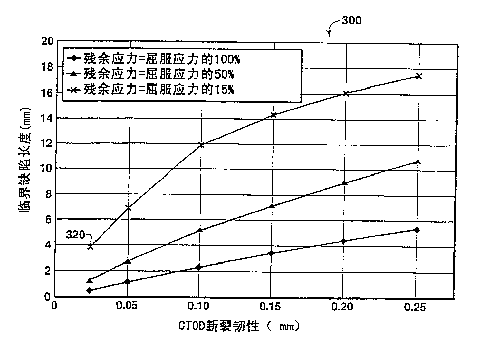
Image

Examples
Embodiment 1
[0053] In a first embodiment of the method of the present invention, gas metal arc welding (GMAW) is used to obtain a weld metal chemical composition comprising iron and about 0.07 wt% carbon, about 2.05 wt% Manganese, about 0.32 wt% silicon, about 2.20 wt% nickel, about 0.45 wt% chromium, about 0.56 wt% molybdenum, less than about 110 ppm phosphorus, and less than about 50 ppm sulfur. A weld is formed on a steel, such as the base steel described above, using an argon-based shielding gas having an oxygen content of less than about 1 wt%. The welding heat input is about 0.3-1.5 kJ / mm (7.6-38 kJ / inch). The tensile strength of the weldment obtained by welding using the present method is greater than about 900 MPa (130 ksi), preferably greater than about 930 MPa (135 ksi), more preferably greater than about 965 MPa (140 ksi), and even more preferably at least about 1000 MPa (145 ksi). Additionally, the DBTT of the weld metal obtained by welding by the present method is less than ...
Embodiment 2
[0055]In another embodiment of the method of the present invention, the GMAW method is used to obtain a weld metal chemical composition comprising iron and about 0.10 wt% carbon (preferably less than about 0.10 wt% carbon, more preferably About 0.07~0.08wt% carbon), about 1.60wt% manganese, about 0.25wt% silicon, about 1.87wt% nickel, about 0.87wt% chromium, about 0.51wt% molybdenum, less than about 75ppm Phosphorus, and less than about 100 ppm sulfur. The welding heat input range is about 0.3-1.5 kJ / mm (7.6-38 kJ / inch), and the preheat temperature used is about 100°C (212°F). A weld is formed on a steel, such as the base steel described above, using an argon-based shielding gas having an oxygen content of less than about 1 wt%. The tensile strength of the weldment obtained by welding using the present method is greater than about 900 MPa (130 ksi), preferably greater than about 930 MPa (135 ksi), more preferably greater than about 965 MPa (140 ksi), and even more preferably ...
Embodiment 3
[0057] In yet another embodiment of the method of the present invention, tungsten inert gas welding (TIG) is used to obtain a weld metal chemical composition comprising iron and about 0.07 wt% carbon (preferably less than about 0.07wt% carbon), about 1.80wt% manganese, about 0.20wt% silicon, about 4.00wt% nickel, about 0.5wt% chromium, about 0.40wt% molybdenum, about 0.02wt% copper, about 0.02 wt% aluminum, about 0.010 wt% titanium, about 0.015 wt% Zr, less than about 50 ppm phosphorus, and less than about 30 ppm sulfur. The welding heat input range is about 0.3-1.5 kJ / mm (7.6-38 kJ / inch), and the preheat temperature used is about 100°C (212°F). A weld is formed on a steel, such as the base steel described above, using an argon-based shielding gas having an oxygen content of less than about 1 wt%. The tensile strength of the weldment obtained by welding using the present method is greater than about 900 MPa (130 ksi), preferably greater than about 930 MPa (135 ksi), more pref...
PUM
| Property | Measurement | Unit |
|---|---|---|
| Tensile strength | aaaaa | aaaaa |
Abstract
Description
Claims
Application Information
 - R&D
- Intellectual Property
- Life Sciences
- Materials
- Tech Scout
- Unparalleled Data Quality
- Higher Quality Content
- 60% Fewer Hallucinations
Browse by: Latest US Patents, China's latest patents, Technical Efficacy Thesaurus, Application Domain, Technology Topic, Popular Technical Reports.
© 2025 PatSnap. All rights reserved.Legal|Privacy policy|Modern Slavery Act Transparency Statement|Sitemap|About US| Contact US: help@patsnap.com