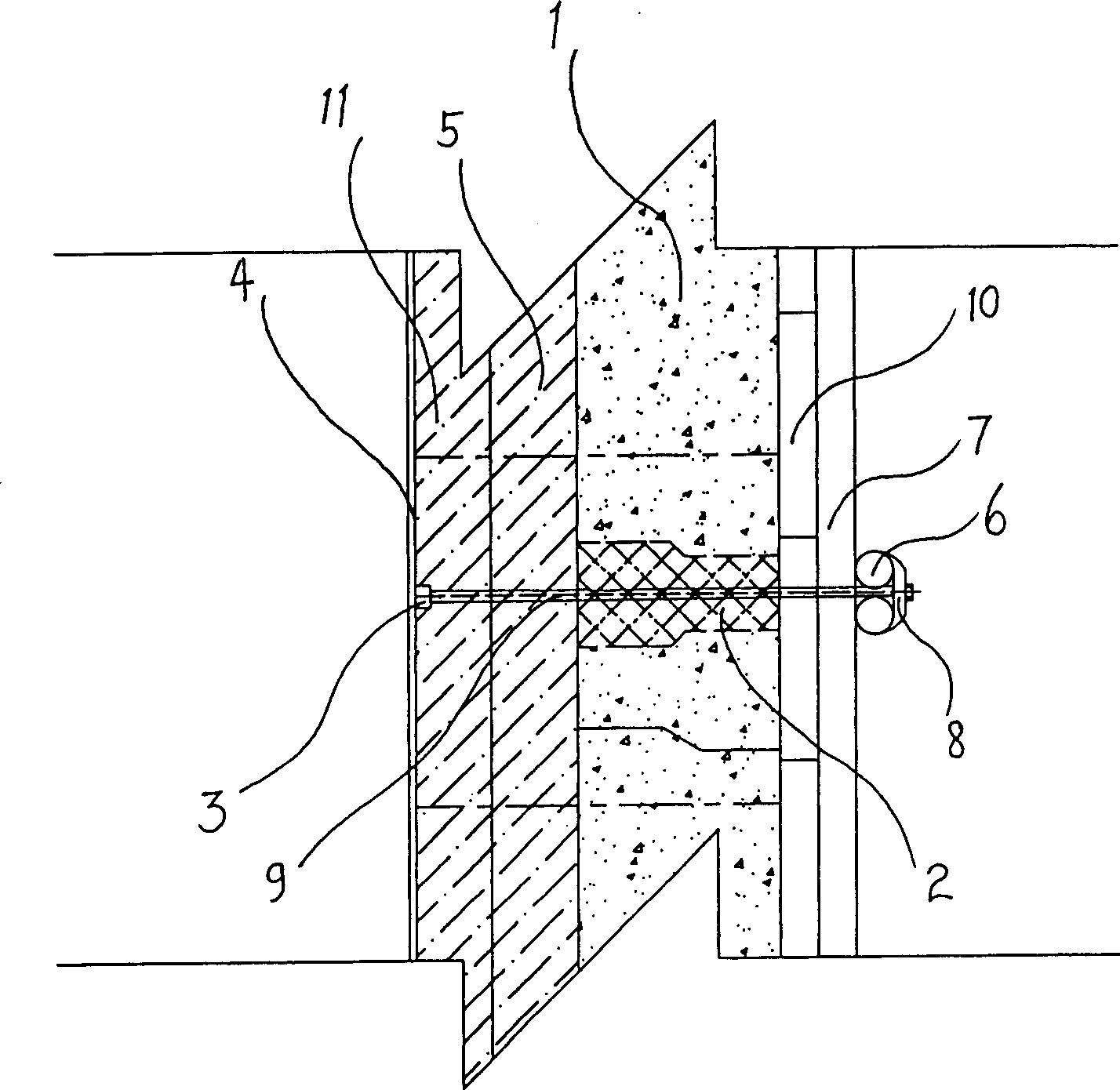
Formwork metthod for paired drawing walls of furnace in integral cast structural furnace
A technology of integral pouring and form-supporting method, applied in the direction of combustion method, building components, building structure, etc., can solve the problem that all the tie bolts cannot be taken out, and achieve the effect of solving the phenomenon of mold expansion, ensuring the integrity and reducing the loss.
- Summary
- Abstract
- Description
- Claims
- Application Information
AI Technical Summary
Problems solved by technology
Method used
Image
Examples
Embodiment 1
[0028] Embodiment 1: The hearth of a walking beam heating furnace is 43200mm long, 14400mm wide and 5000mm high. The thickness of the furnace wall is 100mm insulation board, 116mm lightweight insulation brick and 270mm refractory castable, with a total thickness of 486mm. The method of supporting the formwork with the aid of walking beams is adopted. Implementation situation: Due to the large spacing between the columns of the walking beam and the fact that the upper part of the horizontal beam of the walking beam can only be supported obliquely, the surface of the castable material in the vertical middle part bulges outward, up to 25mm; the surface of the castable material between the columns of the walking beam It bulges outward, up to 10mm, which does not meet the qualification requirements of the national inspection and evaluation standards at all, and the effect is very poor.
Embodiment 2
[0029] Embodiment 2: The hearth of the walking beam heating furnace is 48200mm long, 11400mm wide and 4800mm high. The thickness of the furnace wall is 116mm diatomite insulation brick, 116mm lightweight insulation brick and 270mm refractory castable, with a total thickness of 502mm. The top supporting formwork with the aid of walking beams is adopted, and the casting material is layered and the upper part is pulled against each other. Implementation situation: Since the tie rods must be cut off before the lower formwork is supported, the formwork and the top support will move outward when the tie rods are cut, forming a "Z"-shaped platform at the pouring layer, with a maximum of 12mm. Due to the deflection of the walking beam column itself after being stressed, when the formwork is supported to the height of the horizontal beam, the mold expansion on the surface of the castable still exists. The result is still not up to the qualification requirements of the national inspect...
Embodiment 3
[0030] Embodiment 3: The hearth of the walking beam heating furnace is 46200mm long, 13200mm wide and 4900mm high. The thickness of the furnace wall is 100mm insulation board, 116mm lightweight insulation brick and 250mm refractory castable, with a total thickness of 466mm. The formwork is supported by the walking beam, the double-row beams of the walking beam are connected and fixed, the walking horizontal beam is pulled obliquely to the furnace wall, and the upper part of the pouring material is layered. Implementation situation: Since the tie rods must be cut off before the lower branch film, the formwork and the top support frame will move outward when the tie rods are cut, forming a Z-shaped platform at the pouring layer, with a maximum of 10mm. Since the upper part of the horizontal beam is pulled obliquely to the steel plate of the furnace wall, the expansion of the upper part has been greatly improved. As a result, it barely reached the qualification requirements of t...
PUM
 Abstract
Description
Claims
Application Information
 - R&D
- Intellectual Property
- Life Sciences
- Materials
- Tech Scout
- Unparalleled Data Quality
- Higher Quality Content
- 60% Fewer Hallucinations
Browse by: Latest US Patents, China's latest patents, Technical Efficacy Thesaurus, Application Domain, Technology Topic, Popular Technical Reports.
© 2025 PatSnap. All rights reserved.Legal|Privacy policy|Modern Slavery Act Transparency Statement|Sitemap|About US| Contact US: help@patsnap.com

