Laser machining apparatus

A laser processing and laser technology, which is applied in laser welding equipment, metal processing equipment, optics, etc., can solve the problems of focus distance change, reduced productivity, and processing position offset, etc., to achieve the effect of stabilizing laser processing and avoiding temperature changes

Inactive Publication Date: 2001-03-07
MITSUBISHI ELECTRIC CORP
View PDF0 Cites 40 Cited by
  • Summary
  • Abstract
  • Description
  • Claims
  • Application Information

AI Technical Summary

Problems solved by technology

[0024] Because the conventional laser processing device has the above-mentioned structure, the temperature of the focusing lens 7 fluctuates through the surrounding temperature or the heat generated by the laser processing device itself, which causes the problem that the processing position shifts in approximately proportion to the temperature fluctuation. There is a phenomenon that the processing position deviates by 10-15 μm per 1°C, which becomes a problem of processing failure.
[0025] The deviation of the processing position caused by the aberration of the focus lens 7 can be compensated by the focus lens aberration correction of the above-mentioned coordinate transformation, but when the temperature of the focus lens 7 changes during the aberration correction, the focus lens 7 The optical temporal change, when the temperature rises, such as Figure 52 As shown, the disadvantages of processing that cause the overall shrinkage of the grid points that are actually processed
[0026] In addition, the temperature fluctuation of the focus lens 6 not only causes a shift in the processing position, but also causes a change in the focal length, and the focal point is separated from the working W surface, thereby causing a problem of poor processing position.
[0027] like Figure 53 As shown, when the temperature of the focus lens 7 is T, the laser beam incident on the focus lens 7 is focused by the laser beam La, and the focus point Pa is on the surface of the workpiece W, which can be processed well, but the temperature of the focus lens 7 is only In the case of fluctuations in δT, laser beams at the same incident angle are focused by the laser beam Lb, so the processing position deviates by δX, and the height of the focus point Pb also increases by δf.
[0028] Such a deviation of the processing position cannot be recognized unless the accuracy is checked after processing, and the processing continues in a state where a large number of position deviations are caused, thereby causing a problem of mass production of poorly processed substrates.
[0029] In addition, when the focus lens aberration correction is performed frequently, the deviation of the processing position can be eliminated, but in actual automatic processing, when performing the correction of the focus lens, the operation must be stopped, which reduces productivity.
[0030] Since there is no method of automatically performing deviation detection of the focus distance, the focus distance must be calculated in advance by the operator in actual processing, and if it is constantly changing, there is no effective measure for the change.

Method used


Image

  • Laser machining apparatus
  • Laser machining apparatus
  • Laser machining apparatus

Examples


Embodiment 1

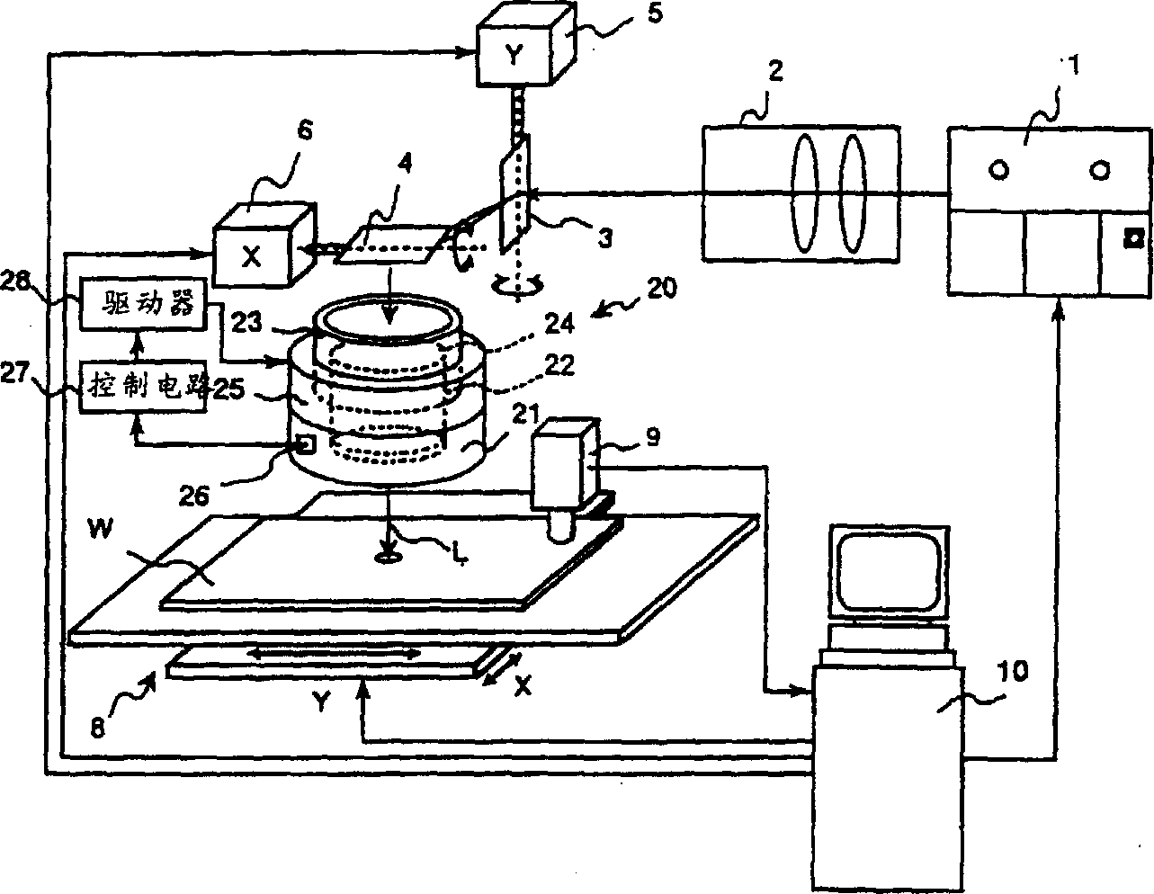
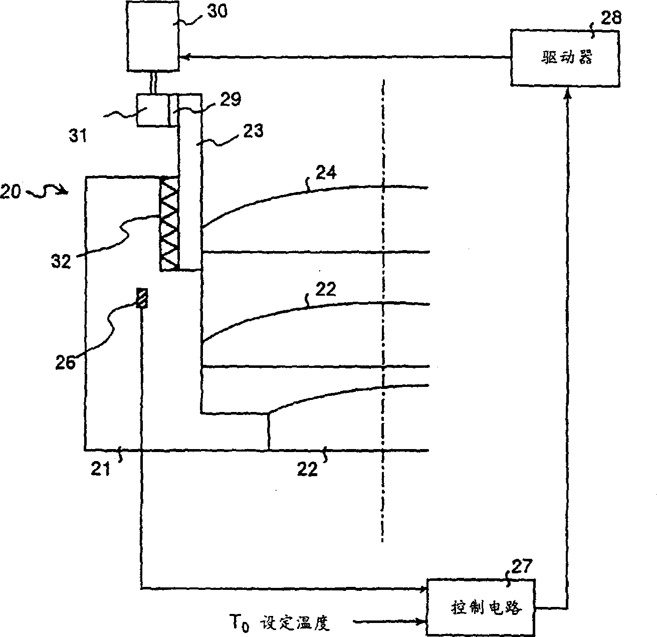
[0165] figure 1 It is an overall configuration diagram showing Embodiment 1 of the laser processing apparatus of the present invention.

[0166] The laser processing apparatus of Example 1 has a lens position adjustment device that changes the relative position between the lenses of the focus lens according to the temperature of the focus lens in order to eliminate the temperature change of the refractive index of the lens of the structure focus lens.

[0167] exist figure 1 , the focusing lens is denoted by reference numeral 20 . The focusing lens 20 is an fθ lens, and injects the laser light L deflected by the Y-axis galvano mirror 3 and the X-axis galvano mirror 4 to focus the laser light as in the conventional device.

[0168] In the laser processing apparatus of the present embodiment, the focus deviation of the focus lens 20 caused by the temperature change of the focus lens 20 is corrected by autofocusing (focusing) compensation.

[0169] Therefore, the focusing le...

Embodiment 2

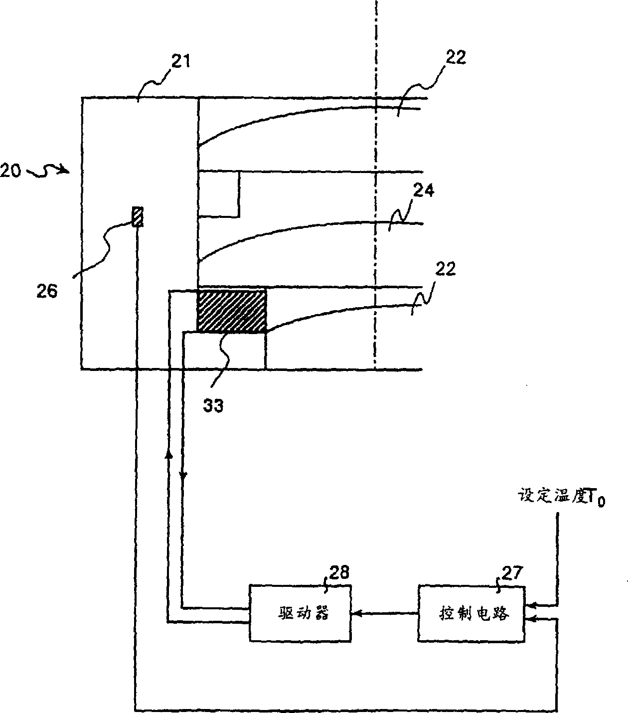
[0179] image 3 It is Example 2 which shows the laser processing apparatus of this invention.

[0180] In the laser processing device of this embodiment, the focus deviation of the focus lens 20 caused by the temperature change of the focus lens 20 is corrected by automatic focusing, and the movable lens 24 is supported on the lens holder 21 by a piezoelectric (piezo) element 33. The electric distortion of the electric element 33 directly displaces the movable lens 24 in the direction of the optical axis.

[0181] The control circuit 27 compares the preset set temperature T0 with the temperature of the focus lens 20 detected by the temperature sensor 26, and the deviation Δf of the focus distance f of the focus lens 20 produced by eliminating the temperature difference A command signal is supplied to the driver 28 of the piezoelectric element 33 in order to displace the movable lens 24 .

[0182] Therefore, the movable lens 24 is moved in the direction of the optical axis co...

Embodiment 3

[0185] Figure 4 It shows Example 3 of the laser processing apparatus of this invention.

[0186] In the laser processing device of this embodiment, the focus deviation of the focus lens 20 caused by the temperature change of the focus lens 20 is corrected by automatic focusing, and the movable lens 24 is supported by the lens holder 21 by the temperature-elasticity holding part 34. Due to the temperature-elasticity The temperature expansion and contraction of the holding fitting 34 directly displaces the movable lens 24 in the direction of the optical axis.

[0187] For the temperature-elasticity holding fitting 34, select a material whose thermal expansion coefficient is negative for the fixed lens 22 and the temperature characteristic of the movable lens 24 (the temperature change rate of the focal distance f), for example, it can be made of calcite (CaCO3) and other structures, and the temperature changes The stretchability of the movable lens 24 displaces in the directio...


PUM


Abstract

A laser machining apparatus comprising a deflector for changing the direction of the laser beam emitted from a laser oscillator and a condenser lens for refracting the laser beam incident thereon from the deflector and forming an image on a work as the machining object, wherein lens position adjustment means capable of changing the relative positions of a plurality of lenses comprising the condenser lens by a condenser lens temperature is assembled into the apparatus, and this lens position adjustment means changes the relative positions of a plurality of lenses by the condenser lens temperature in such a manner as to offset the change of the refractive index of the lenses with temperature.

Description

technical field [0001] The present invention relates to a laser processing device, in particular to a laser processing device for drilling, cutting, and marking resin materials such as printed circuit boards and semiconductor chips (chips) or ceramic materials. Background technique [0002] As a laser processing device for performing drilling, cutting, marking, etc., known conventional Figure 46 structure shown. [0003] This laser processing apparatus includes, as an optical system: a laser oscillator 1 as a source of laser light L, a collimator lens (collimate lens) 2 for adjusting the divergence angle of the laser light, and aligning the direction of the laser light L in accordance with the rotation angle. Y-axis galvanomirror (galvanomirror) 3 and X-axis galvanomirror 4 deflected in any direction, and Y-axis galvano-scanner that adjusts the rotation angles of Y-axis galvanomirror 3 and X-axis galvanomirror 4 according to the processing program (galvano scanner) 5, an X...

Claims


Application Information

Patent Timeline
IPC IPC(8): B23K26/064G02B1/04G02B3/00
Inventor 鉾馆俊之祝靖彦黑泽满树西前顺一田中健太郎
Owner MITSUBISHI ELECTRIC CORP
Why Eureka
Try Eureka