Charging control system for trolleybus charged in station zone

A trolleybus, charging control technology, applied in electric vehicles, current collectors, electric traction and other directions, can solve the problem of not involving the composition principle, not finding the charging control technology of the trolleybus system, etc.

Inactive Publication Date: 2006-12-13
SHANGHAI JIAOTONG UNIV
View PDF1 Cites 0 Cited by
  • Summary
  • Abstract
  • Description
  • Claims
  • Application Information

AI Technical Summary

Problems solved by technology

"Although this invention mentions trolleybus parking and charging at the station area, and "the lifting and charging process of the trolleybus pantograph is fully automated, as long as the driver manipulates the tram into the traffic sign boundary line on the road in the station area when it is at the station." , so the driver’s workload will not be increased. If the vehicle in front fails in the station, the driver of the vehicle behind can also manually intervene in the power receiving switch device on the tram to control the lowering of the pantograph, and drive the vehicle out of the stop by bypassing the faulty vehicle. It is not affected by the vehicle in front,” but it does not involve the composition principle of the sensor, control system and power switch of the electric car on the electric car, and the technical method to realize the charging control, so the application of this technology is still insufficient to a certain extent. Deficiencies; so far no charge control technology has been found for charging trolleybus systems in station areas

Method used


Image

  • Charging control system for trolleybus charged in station zone
  • Charging control system for trolleybus charged in station zone

Examples


Embodiment Construction

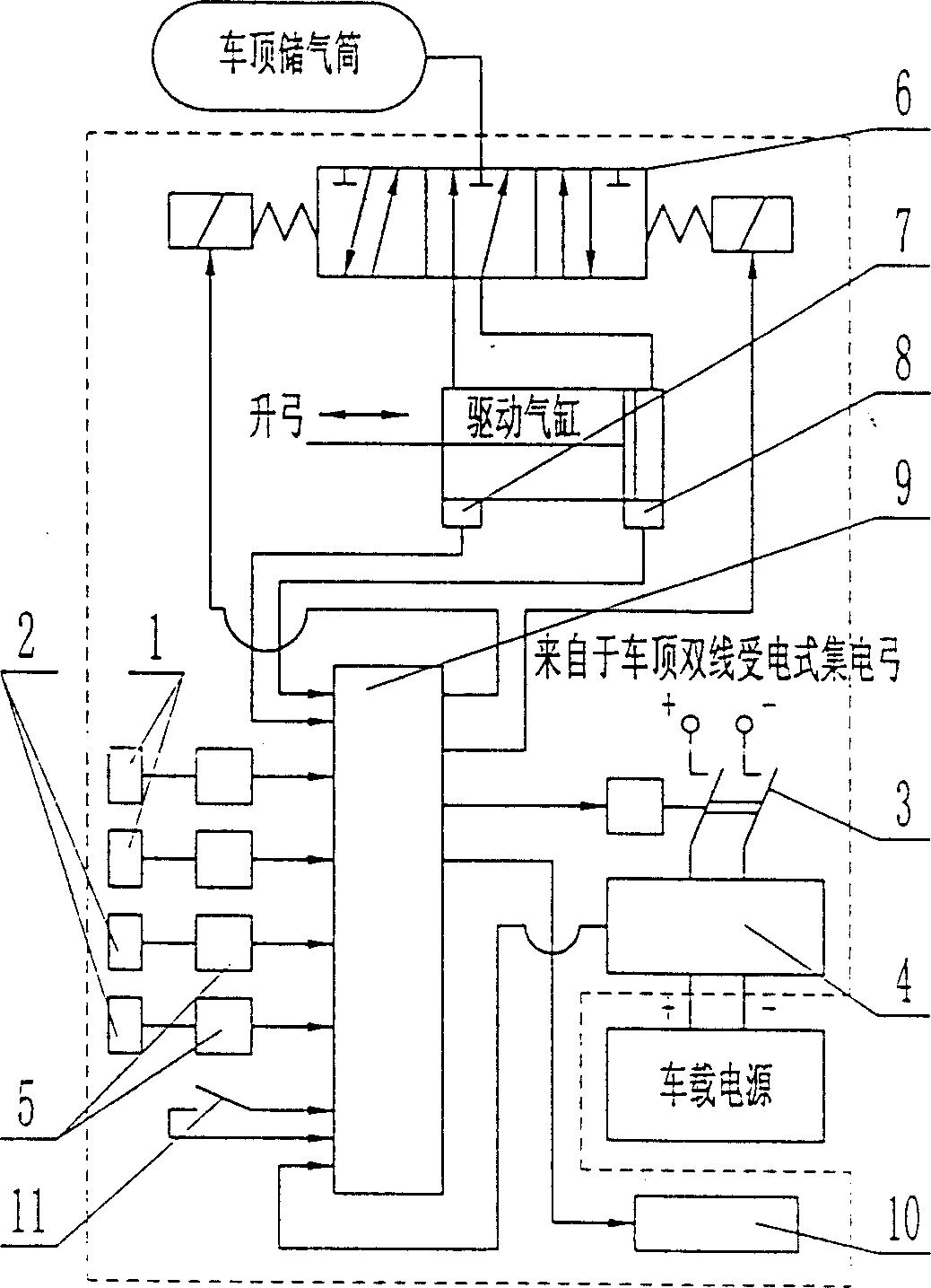
[0014] like figure 1As shown, the present invention includes: a left vehicle position detection sensor 1, a right vehicle position detection sensor 2, a double power receiving switch 3, a large current fast charging device 4 with a power state monitor, a signal conditioning amplifier 5, a middle One-position exhaust type three-position five-way solenoid valve 6, rising end magnetic travel switch 7, descending end magnetic travel switch 8, power receiving controller 9, display 10, manual lowering bow switch 11, and its connection and fixing method is: left vehicle The position detection sensor 1 and the vehicle position detection sensor 2 on the right are respectively arranged on the left and right sides of the bottom of the rechargeable trolleybus near the front of the car, the double-connected power receiving switch 3, and the high-current fast charging device 4 with a power supply status monitor , signal conditioning amplifier 5, power receiving controller 9 are installed in...


PUM


Abstract

An electric charge control system for the trolley bus charged at charging station is composed of left and right vehicle position detecting sensors, double receiving switch, high-current fast charger with power supply state monitor, 3-position-5-way electromagnetic valve, lifting and lowering magnetic stroke switch, receiving controller, display, and manual switch for lowering bow.

Description

technical field [0001] The invention relates to a charging control system for a trolleybus, in particular to a charging control system for a charging type trolleybus in a station area as an urban public transportation tool, which is used in the field of urban public transportation engineering. Background technique [0002] The rechargeable trolleybus in the station area used for urban public transportation uses large-capacity battery packs or supercapacitor energy storage as the power source for driving the motor. During the period of entering and stopping at the station, it is necessary to obtain electric energy for a short time from the special trolley bus catenary for charging in the station area overhead above the station area road, and recharge the on-board battery pack or super capacitor; the charging electric energy is passed through the automatic power receiving equipment on the roof of the trolley bus —The pantograph of the double-line powered trolleybus is introduc...

Claims


Application Information

Patent Timeline
Patent Type & Authority Patents(China)
IPC IPC(8): B60L11/18B60L5/00
CPCY02T10/7088Y02T10/7005Y02T10/70
Inventor 程晓鸣
Owner SHANGHAI JIAOTONG UNIV
Why Eureka
Try Eureka