Method for providing a component of a large machine with a protective coating

A technology of machine components and protective layers, applied in the direction of engine components, machines/engines, valve devices, etc., to avoid internal stress, high stability, and time saving

Inactive Publication Date: 2007-08-08
MAN DIESEL & TURBO FILIAL AF MAN DIESEL & TURBO SE TYSKLAND
View PDF6 Cites 0 Cited by
  • Summary
  • Abstract
  • Description
  • Claims
  • Application Information

AI Technical Summary

Problems solved by technology

In addition, the interruption of the welding process induces a cert

Method used


Image

  • Method for providing a component of a large machine with a protective coating
  • Method for providing a component of a large machine with a protective coating

Examples


Embodiment Construction

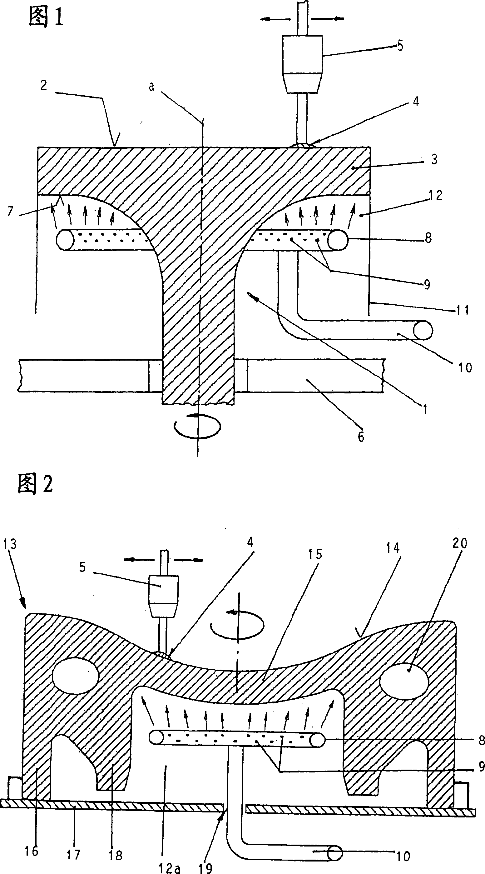
[0016] The main field of application of the present invention is to configure a protective layer processed by overlay welding for large machines, such as components of two-stroke large diesel engines, wherein the protective layer to be coated has a rather heavy mass of at least 10 kg, for a two-stroke large diesel engine This is often the case with the exhaust valves or the protection of the piston crowns of large stroke diesel engines.

[0017] Figure 1 shows an exhaust valve 1 of a two-stroke large diesel engine. This can be, for example, a vent valve suitable for an 80 cm hole. On the underside 2 of its valve disk 3 facing the combustion chamber during operation, this exhaust valve is provided with a protective layer 4 , for example of a nickel alloy, which is applied by means of a welding device 5 in a build-up welding process. The welding device 5 can be a gas shielded welding device (GMAW) or an electroslag welding device (ESW).

[0018] The welding device 5 is equippe...


PUM


Abstract

The invention relates to a method for providing a component of a large machine, especially a piston head or an outlet valve head of a large two-stroke diesel engine, with a protective coating (4) which is applied to the corresponding surface (2 or 14) by means of surfacing. According to the ivnention, the method can be carried out in an economical and careful manner due to the fact that the large machine component provided with the protective coating (4) is cooled during the surfacing process.

Description

technical field [0001] The invention relates to a method for providing large machine components, in particular piston crowns or exhaust valve disks of a large two-stroke diesel engine, with a protective layer which is applied to the associated surfaces by overlay welding. Background technique [0002] When carrying out a method of the type described above, a very severe thermal load is produced on the component to be provided with the protective layer due to the welding process. There is therefore the risk of exceeding the permissible temperatures of the aforementioned component materials. In the case of protective coverings of large machine components of the type described above, this risk is particularly great when the covering has a relatively high mass. [0003] For this reason, the welding process has to be interrupted several times in order to allow the components to cool down during the production of the protective layer by overlay welding. This is time consuming an...

Claims


Application Information

Patent Timeline
IPC IPC(8): F02F3/12F02F3/14B23K9/04F01L3/04F01L3/24F02B3/06F02F1/00F02F3/00F02F3/10F16J1/01
CPCF02B3/06F02F2007/0097F02F3/14B23K2201/003F02F3/12B23K9/046B23K2101/003Y02T10/12B23K9/04
Inventor 哈罗·A·赫格
Owner MAN DIESEL & TURBO FILIAL AF MAN DIESEL & TURBO SE TYSKLAND
Why Eureka
Try Eureka