Method and wire for reducing or eliminating resistance in power transmission line

A technology for power transmission lines and resistance, which is applied in the field of reducing or eliminating the resistance of power transmission lines, and can solve problems such as power loss, density influence, multi-consumption of non-ferrous metal materials, etc., to achieve the effects of reducing consumption, increasing density, and eliminating power loss

Inactive Publication Date: 2002-02-27
马龙
View PDF0 Cites 2 Cited by
  • Summary
  • Abstract
  • Description
  • Claims
  • Application Information

AI Technical Summary

Problems solved by technology

[0002] Reducing the temperature of the conductor material can reduce the resistivity of the conductor material, or eliminate the resistivity to make it a superconductor, but due to the influence of the superconductor material's use temperature is too low, it is not yet practical to use superconductor materials to erect long-distance power transmission lines. It is not practical to reduce the temperature of conductor materials to reduce the resistivity of power transmission lines. At present, the long-distance transmission of electric energy is carried out by wires made of low-resistivity copper, aluminum and other materials. Due to the existence of resistance , the density of electric energy transmitted by the power transmission line is greatly affected, and it has to rely on increasing the cross-sectional area of ​​the wire of the power transmission line to reduce the resistance and transmit more electric energy. The resistance of the long-distance high-voltage power transmission line will cause a large amount of power loss; the power loss caused by the resistance of the long-distance high-voltage power transmission line accounts for about 10% of the transmitted power, resulting in waste of power and indirectly increasing environmental pollution.

Method used


Image

  • Method and wire for reducing or eliminating resistance in power transmission line
  • Method and wire for reducing or eliminating resistance in power transmission line
  • Method and wire for reducing or eliminating resistance in power transmission line

Examples


Embodiment Construction

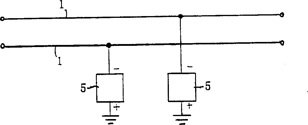
[0020] The method for reducing or eliminating the resistance of the power transmission line of the present invention includes making a lead 1 with a conductive material, connecting the negative pole of the electrostatic generator 5 or the high-voltage DC power supply 5 to the lead 1 of the power transmission line, and connecting the electrostatic generator 5 or the high-voltage The positive pole of the DC power supply 5 is grounded, and at least one electrostatic generator 5 or high-voltage DC power supply 5 is utilized to deliver negative charges to the lead 1, so that the lead 1 has a negative charge. According to the theory of quantum mechanics, the negative charge on the lead 1 will tend to Electron pairs are composed of electrons with parallel and opposite spins, and the negative charges on the wire 1 and / or electron pairs composed of negative charges are used to transmit electromagnetic field energy, and the resistivity of the wire 1 will be reduced or eliminated.

[0021...


PUM


Abstract

The method for reducing and eliminating power transmission line resistance includes the following measures: connecting static electrizer or negative electrode or high voltage D.C. power supply with powre transmission line; making static electrizer or positive electrode of high-voltage D.C. power supply grounding; utilizing at least one static electrizer or high-voltage D.C. power supply to transmit negative charge to power line, making the negative charge on the line and reverse electrons form electron pair and utilizing negative charge and/or electron pair formed from negative charge to transmit electric energy. Because, the inertial-mass of electron pair is small, its thermal movement and crystal lattice formed into line do not produce heat exchange, and the electron pair can stably exist at normal temp. state. and the cross-section of the invented transmission line is made into peach-shaped column structure, and said transmissino line can be erected in the pipeline filled with high-pressure gas. The invented method can reduce or eliminate electric energy loss resulted from resistance in the power transmission.

Description

technical field [0001] The invention relates to a method and electric wire for reducing or eliminating the resistance of a power transmission line. Background technique [0002] Reducing the temperature of the conductor material can reduce the resistivity of the conductor material, or eliminate the resistivity to make it a superconductor, but due to the influence of the superconductor material's use temperature is too low, it is not yet practical to use superconductor materials to erect long-distance power transmission lines. It is not practical to reduce the temperature of conductor materials to reduce the resistivity of power transmission lines. At present, the long-distance transmission of electric energy is carried out by wires made of low-resistivity copper, aluminum and other materials. Due to the existence of resistance , the density of electric energy transmitted by the power transmission line is greatly affected, and it has to rely on increasing the cross-sectional ...

Claims


Application Information

Patent Timeline
Patent Type & Authority Applications(China)
IPC IPC(8): H02G7/00H02J1/00H02J3/00
Inventor 马龙
Owner 马龙
Why Eureka
Try Eureka