

Nevigation-class cyclic interference type integrated optical gyroscope
An integrated optics and interferometric technology, applied in the direction of steering sensing equipment, etc., can solve the problems of high cost, shorten the length of the optical fiber sensitive coil, etc., achieve the effect of reducing sensitivity, reducing spontaneous radiation noise, and improving signal-to-noise ratio
- Summary
- Abstract
- Description
- Claims
- Application Information
AI Technical Summary
Problems solved by technology
Method used
Image

Examples
Embodiment 1
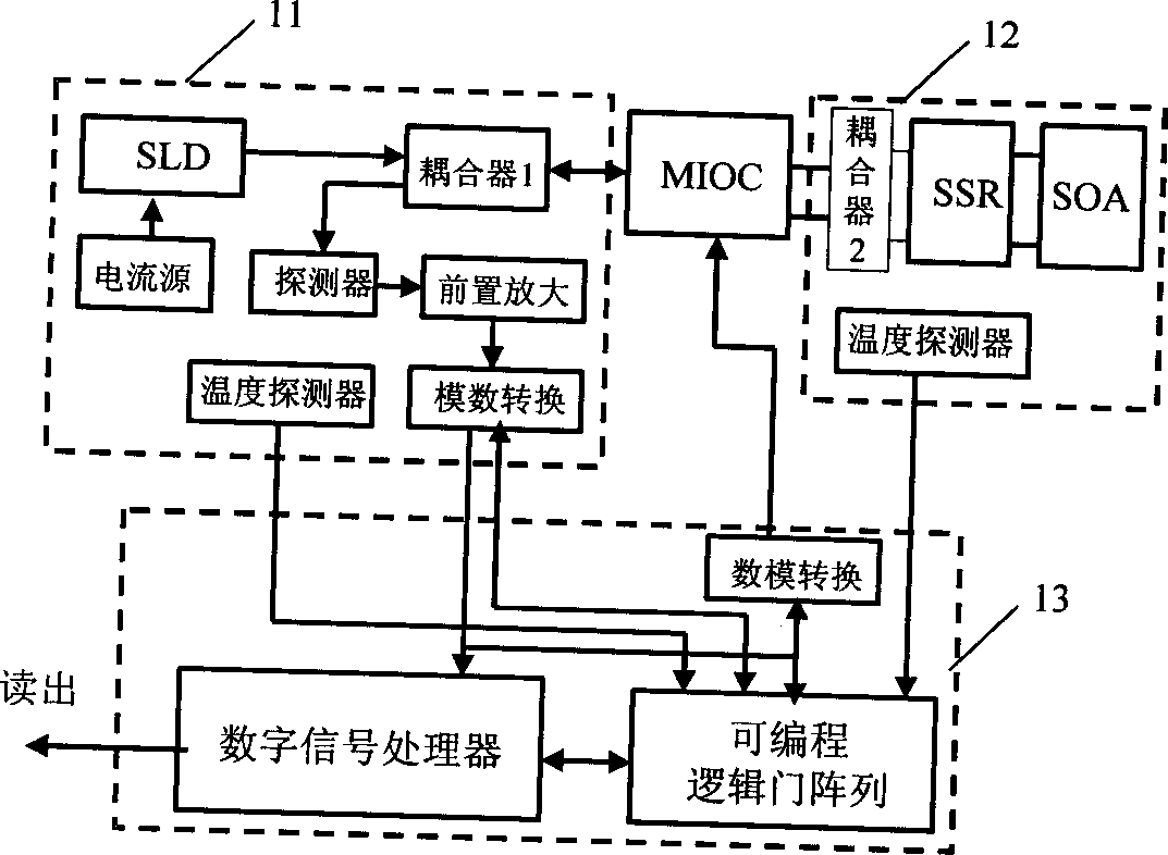
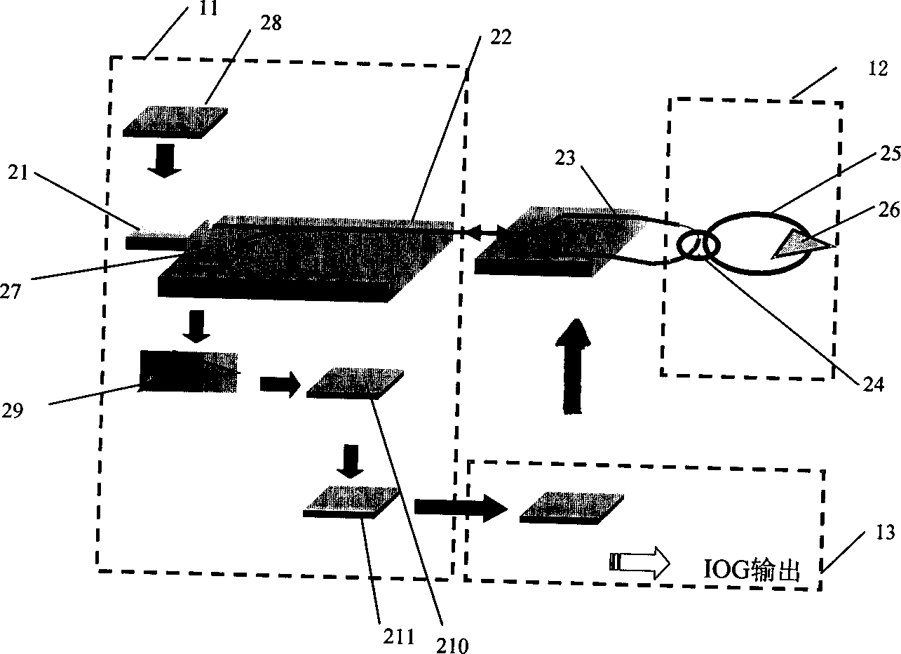
[0033] Embodiment 1 is a navigation level circular interference type integrated optical gyroscope (IOG) using an optical fiber SSR module, and its structure is as follows figure 2 As shown, the optical system of this IOG includes a superluminescent light-emitting diode SLD21 in the optical transceiver module, an MIOC module 23 and an optical fiber SSR module with an SOA. The low-coherent light wave emitted by SLD21 is sent to MIOC23 through Y waveguide coupler 22, and then enters optical fiber SSR25 through coupler 24. The light wave is amplified by SOA26 in the SSR and propagates in clockwise and anticlockwise directions. The output signal of the SSR enters the photodetector 27 through the coupler 24 , the MIOC and the coupler 22 .
[0034] The circuit system of this embodiment includes the current source of the light source in the optical transceiver module and the temperature control circuit 28, the signal preprocessing circuit of the photodetector (including the preampli...
Embodiment 2
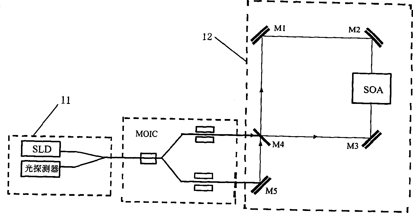
[0037] Embodiment 2 is a navigation level circular interference type integrated optical gyroscope (IOG) using a micro-optical SSR module, and its structure is as follows image 3 shown. In this IOG, the structure of optical transceiver module and MIOC module is the same as figure 2 The structure is exactly the same, the SSR module adopts the form of micro-optical structure, in which, a micro-optical structure of high reflective mirrors M1, M2 and M3 and half-transparent and half-reflective mirror M4 are set at each of the four corners of the quadrangle to form a sensitive sensor for the Sineck effect. ring, a semiconductor optical amplifier (SOA) is set on the optical path between the two mirrors M2 and M3; it also includes a high reflection mirror M5 arranged in one optical path of the MIOC module and the reflection optical path of M4, and the M4 is located In the other optical path of the MIOC module, M4 and M5 form a coupler 2, which couples the interference signals of the ...
Embodiment 3
[0039] Embodiment 3 is a navigation level circular interference type integrated optical gyroscope (IOG) using optical waveguide SSR, its structure is as follows Figure 4 shown. In this IOG, the optical waveguide is used to replace the optical fiber in Embodiment 1 to form the SSR module, and the rest are the same as figure 2 The structure is exactly the same, it is characterized by miniaturization, and the SSR and SOA of the optical waveguide can be integrated on the same substrate.
[0040] The optical transceiver module of the Y-waveguide coupler that adopts in each above-mentioned embodiment, its structure is as follows Figure 5 As shown in the figure, the SLD31 is welded on the copper heat sink 32, connected to the housing 34 through the semiconductor refrigerator 33, the light wave emitted by the SLD is coupled into a branch of the Y-waveguide coupler 36 through the microlens 35, and in the Y- The other end of the waveguide coupler is coupled with the fiber pigtail 3...
PUM
 Abstract
Description
Claims
Application Information