Powe supply unit and air conditioner with the power supply unit

A technology for power supply devices and capacitors, applied in electrical components, output power conversion devices, applications, etc., can solve problems such as inability to share circuits, adverse effects of load 105, and increased choke coil losses.

Inactive Publication Date: 2002-07-10
PANASONIC CORP
View PDF2 Cites 12 Cited by
  • Summary
  • Abstract
  • Description
  • Claims
  • Application Information

AI Technical Summary

Problems solved by technology

[0011] However, in the Figure 26 In the conventional power supply device shown, although the power factor can be improved with a simple structure, the improvement effect is small, and a satisfactory power factor cannot be obtained.
Moreover, there is also the following problem: in order to obtain a high power factor with this circuit structure, the value of the choke coil needs to be increased, which will lead to an increase in the size of the structural components and the resulting increase in loss
In addition, when switching the energized state of the relay circuit 130, the output voltage changes greatly, which may adversely affect the load 105.
[0012] in addition, Figure 27 In the power supply unit shown, although the power factor can be greatly improved by simple switch control, when the power supply unit is used in an air conditioner, etc., there are the following problems: First, when the input When the choke coil is 200V, the loss in the choke coil increases due to the enlargement of the choke coil; second, because the size of the choke coil is different when the input is 100V and when the input is 200V, the circuit cannot be shared; Three, when switching the energized state of the relay circuit 130, the output voltage changes greatly, which may bring adverse effects to the load 105

Method used


Image

  • Powe supply unit and air conditioner with the power supply unit
  • Powe supply unit and air conditioner with the power supply unit
  • Powe supply unit and air conditioner with the power supply unit

Examples


Embodiment 1

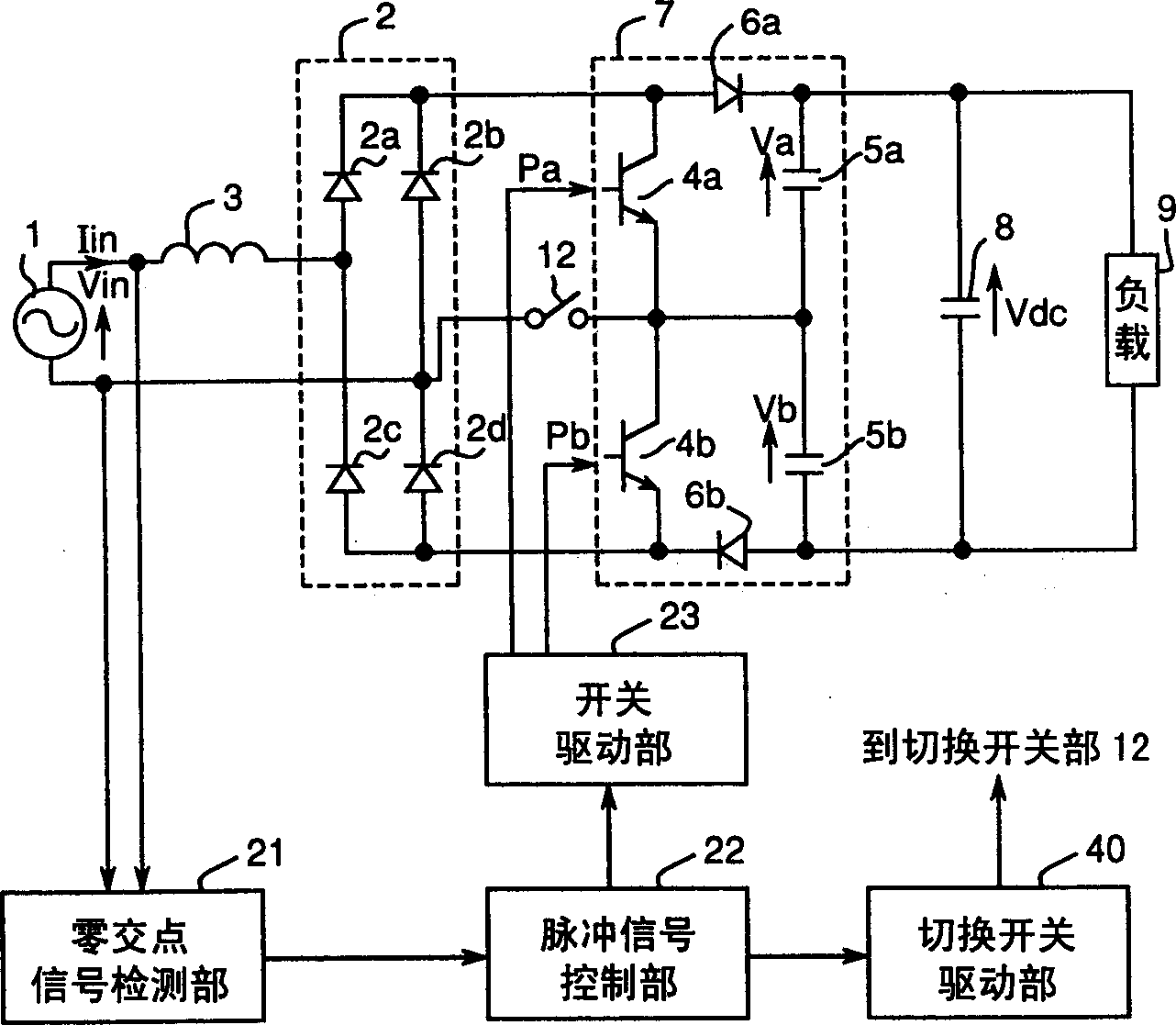
[0059] figure 1 is a circuit configuration diagram showing an embodiment of the power supply unit in the present invention. exist figure 1 Among them, the power supply unit is composed of an AC power supply 1 , a rectifier circuit 2 , a choke coil 3 , a power factor improvement circuit 7 , a smoothing capacitor 8 and a switch unit 12 .

[0060] The power factor improving circuit 7 is composed of two switching elements 4a, 4b, two capacitors 5a, 5b, and two backflow preventing rectifying elements 6a, 6b. The midpoint of the series connection of the two switching elements 4a, 4b and the midpoint of the series connection of the two capacitors 5a, 5b are connected. The switching element 4a and the capacitor 5a are connected together through the backflow prevention rectification element 6a, and the switching element 4b and the capacitor 5b are connected together through the backflow prevention rectification element 6b.

[0061] The changeover switch unit 12 is connected betwee...

Embodiment 2

[0083] Image 6 , Figure 7 with Figure 8 It is a circuit configuration diagram showing another embodiment of the power supply device of the present invention. exist Image 6 , Figure 7 with Figure 8 In the power supply unit shown, the figure 1 In addition to the circuit structure shown, a voltage polarity determination unit 41 for determining the polarity of the voltage Vin of the AC power supply 1 is added.

[0084] The voltage polarity determination unit 41 determines the polarity of the voltage at the other end of the connection point with the changeover switch unit 12 at the AC input terminal of the rectifier circuit 2 . Further, the changeover switch driving unit 40 receives the switching signal from the pulse signal control unit 22 and changes the energization state of the changeover switch unit 12 to ON or OFF. Below, describe in detail Image 6 , Figure 7 with Figure 8 power supply unit shown.

[0085] Figure 9 expressed Image 6 In the power suppl...

Embodiment 3

[0100] Figure 13 It is a circuit structure diagram of another embodiment of the power supply device of the present invention. Figure 13 The power supply unit in the figure 1 In the circuit structure shown, an input power detection unit 42 is added.

[0101] The input power detection unit 42 is provided at the front of the rectification circuit 2 , detects the value of the AC current Iin, and outputs it to the pulse signal control unit 22 .

[0102]In order to suppress the impact on the input current waveform when changing the energized state of the switching unit 12 as much as possible, the pulse signal control unit 22 keeps the conduction route of the input current Iin unchanged before and after switching, and operates without affecting the current waveform, that is, the power factor. The pulse signal is controlled to switch the energized state of the switch unit 12 at the timing.

[0103] The influence can be minimized by selecting the current non-conduction period aft...


PUM


Abstract

The invention provides a power supply unit wherein the conduction angle of input current is widened through simple control and thereby the power factor is improved and the harmonic component of the input current is reduced. The power supply unit is provided with a rectification circuit that rectifies the voltage of alternating-current power supply, a reactor connected with the rectification circuit, a power-factor improvement circuit that includes a plurality of switching elements and capacitor circuits and is fed as input with the output voltage of the rectification circuit, a change-over switch portion that is connected between the rectification circuit and the power-factor improvement circuit and switches the state of conduction of a current path formed between them from the state in conduction to the state out of conduction and vice versa, a change- over switch control portion that controls the state of conduction of the change-over switch portion, a pulse signal control portion that generates and outputs pulse signals for turning on and off the individual switching elements in the power-factor improvement circuit, and a switch driving portion that receives the pulse signals from the pulse signal control portion and drives the switching elements in the power-factor improvement circuit.

Description

technical field [0001] The invention relates to a power supply device which converts alternating current into direct current, reduces high-order harmonic components of input current, improves power factor, and provides required power supply voltage and an air conditioner using the power supply device. Background technique [0002] In the past, as an AC-DC conversion circuit, a capacitor input rectifier circuit has been used in various fields. It inputs AC voltage into a diode rectifier circuit to obtain a pulsating current output, and uses a capacitor to smooth the pulsating current to obtain a DC voltage. In the capacitor input type rectifier circuit, because the current conduction angle of the input current is narrowed, the power factor is poor, and the reactive power is large, so not only the power cannot be used effectively, but also there are many high-order harmonic components, which are harmful to the connection to the Machines in the same power system constitute obst...

Claims


Application Information

Patent Timeline
Patent Type & Authority Applications(China)
IPC IPC(8): F24F11/02H02M1/08H02M1/14H02M7/12H02M7/21H02M7/48
CPCH02M1/42H02P27/06
Inventor 奥井博司小川正则
Owner PANASONIC CORP
Why Eureka
Try Eureka