Optical recording media and manufacturing thereof
An optical recording medium and recording layer technology, which is applied in the manufacture of optical record carriers, optical record carriers, and duplication/marking methods, etc., can solve the problem of signal leakage of ground pits, errors in RF signal readout, and leakage of ground pre-pit signals. RF signal, etc.
- Summary
- Abstract
- Description
- Claims
- Application Information
AI Technical Summary
Problems solved by technology
Method used
Image
Examples
Embodiment 1
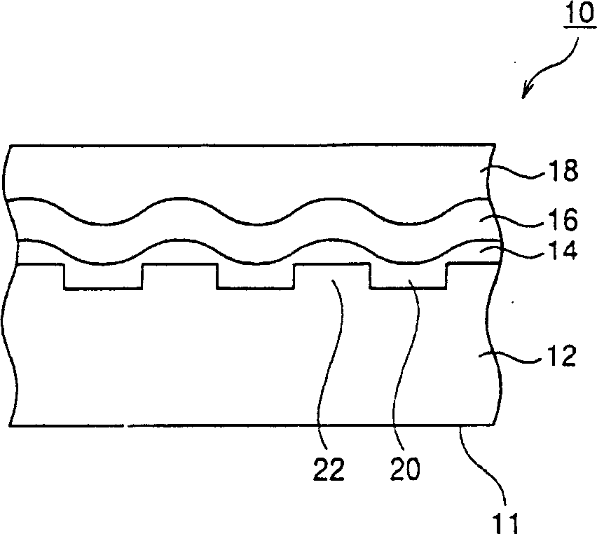
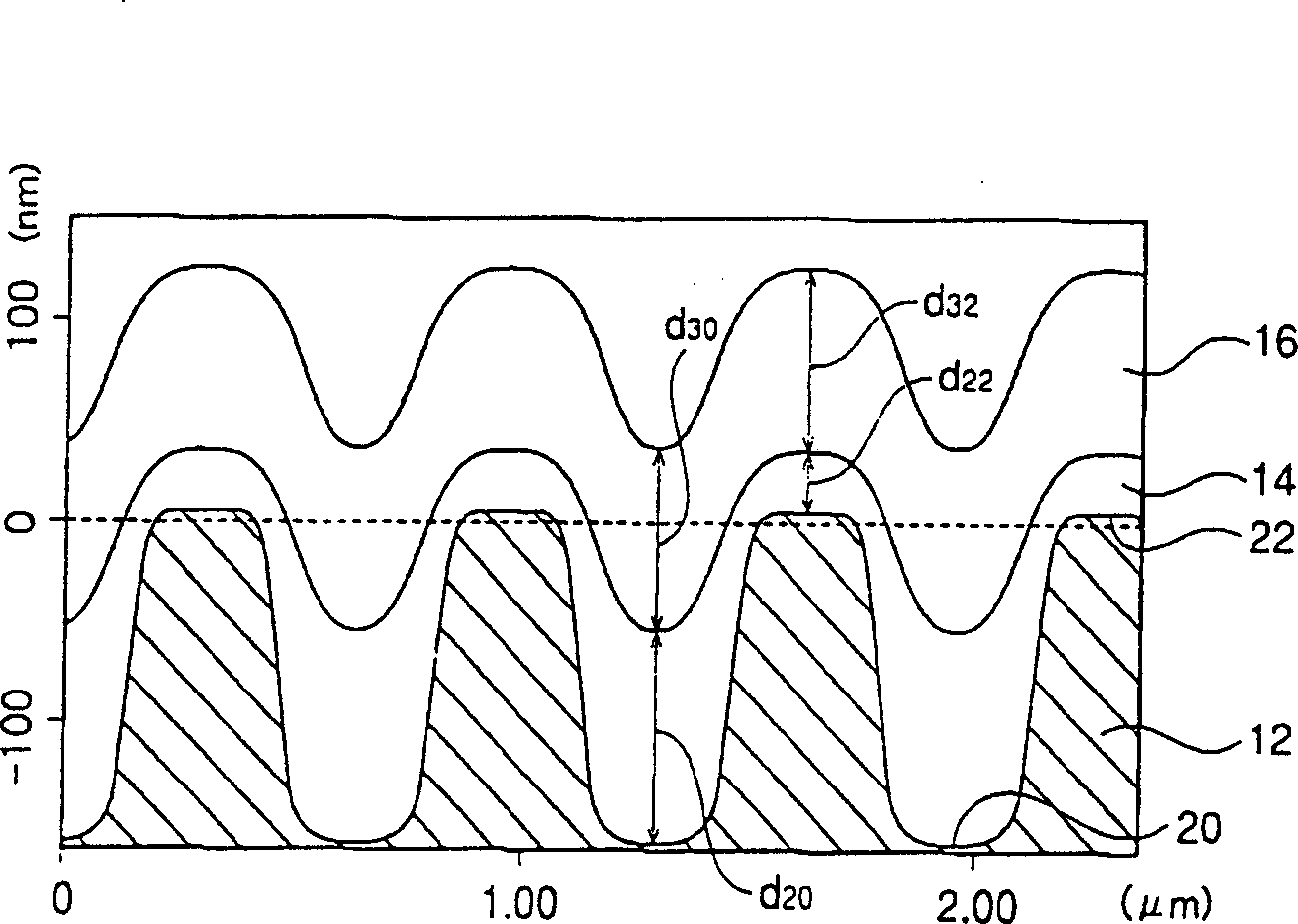
[0093] A polycarbonate sheet for DVD·R with a diameter of 120 mm and a thickness of 0.6 mm was used as a transparent resin substrate on which periodic Z-shaped tracking grooves (pitch: 0.74 μm, depth: 160 nm, width (half-wave width) were provided. ): 350 nm).
[0094] In forming the recording layer, in a solvent comprising 1,2-dimethylcyclohexane (DMCH) mixed with 10% by weight of cyclooctane, a dipyrrolemethylene metal complex dye of the following formula is dissolved in an amount of 20g / L:
[0095] The obtained solution was filtered and applied on the above-mentioned substrate by spin coating, and the thickness of the dye film in the central area of the groove (the thickness of the recording layer) was 120 nm by adjusting the rotational speed.
[0096] The dye thin film thus formed was dried at 80° C. for 1 hour, and a 100 nm-thick Au film was applied as a reflective layer using a sputtering apparatus (model CDI 900, manufactured by Balzers).
[0097] Then, a UV-curabl...
Embodiment 2
[0101] The same substrates and dyes as described in Example 1 were used. The dye was dissolved in a mixed solvent comprising ethylcyclohexane (ECH) and 3% by weight of o-xylene and 10% by weight of cyclooctane at a concentration of 25 g / L. The prepared solution was coated on a substrate, and the rotation adjustment was adjusted so that the film thickness (recording layer thickness) in the central region of the groove was 120 nm. In the same manner as in Example 1, an optical recording medium was prepared, and its signal evaluation was performed. The results are listed in Table 1.
Embodiment 3
[0103] The same substrate as described in Example 1 was used. The pyrrole methylene metal complex of the following formula (3) was dissolved in a mixture comprising a mixture of ethylcyclohexane (ECH) and cyclohexane (mixed in a weight ratio of 3:1) mixed with 5% by weight of cyclooctane. In the solvent, the concentration is 15g / L. The prepared solution was coated on the substrate, and the rotation adjustment was adjusted so that the film thickness (recording layer thickness) in the central region of the groove was 120 nm. In the same manner as in Example 1, an optical recording medium was prepared, and its signal evaluation was performed. The results are listed in Table 1.
PUM
| Property | Measurement | Unit |
|---|---|---|
| thickness | aaaaa | aaaaa |
| boiling point | aaaaa | aaaaa |
| diameter | aaaaa | aaaaa |
Abstract
Description
Claims
Application Information
 - R&D
- Intellectual Property
- Life Sciences
- Materials
- Tech Scout
- Unparalleled Data Quality
- Higher Quality Content
- 60% Fewer Hallucinations
Browse by: Latest US Patents, China's latest patents, Technical Efficacy Thesaurus, Application Domain, Technology Topic, Popular Technical Reports.
© 2025 PatSnap. All rights reserved.Legal|Privacy policy|Modern Slavery Act Transparency Statement|Sitemap|About US| Contact US: help@patsnap.com


