
Soft switching whole bridge connection circuit converter

A bridge circuit and converter technology, which is applied in the field of constant-frequency isolated dc/dc complete bridge circuit converters, can solve problems such as circuit 100 duty cycle loss, and achieve improved efficiency, reduced secondary side oscillation, and reduced power loss Effect

Inactive Publication Date: 2002-08-21
DELTA ELECTRONICS INC
View PDF1 Cites 19 Cited by
  • Summary
  • Abstract
  • Description
  • Claims
  • Application Information

AI Technical Summary

Problems solved by technology

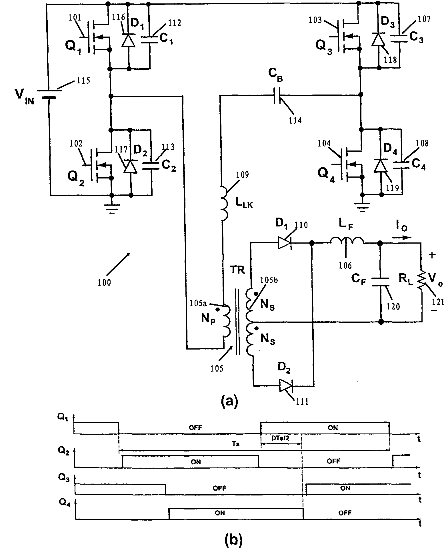
[0009] because figure 1 In order to realize the ZVS state, the circuit 100 in the circuit 100 needs to increase the leakage inductance or an external inductance (or both) in series with the transformer, so the circuit 100 has a large loss in the secondary side duty cycle

Method used


Image

  • Soft switching whole bridge connection circuit converter
  • Soft switching whole bridge connection circuit converter
  • Soft switching whole bridge connection circuit converter

Examples


Embodiment Construction

[0025] Figure 4 An isolated dc / dc FB ZVS PWM converter 400 including a coupled inductor 403 on the primary side of a transformer 401 in accordance with the present invention is shown. The converter 400 achieves a ZVS state at the primary switches 101-104 even at low load current conditions and with minimal cycling energy and conduction losses. exist Figure 4 In , switches 101-104 are connected to coupled inductor 403 and transformer 401 through DC blocking capacitors 114a and 114b. DC blocking capacitors 114a and 114b prevent DC current from flowing, thus preventing saturation of coupled inductor 403 and transformer 401 . Capacitors 114a and 114b are selected to have sufficiently large values ​​so that their voltages are approximately constant during the switching cycle. For relative load variation or at constant switching frequency the input voltage V in To change and adjust the output voltage Vo, a phase shift control circuit (not shown in the figure) is provided. exi...


PUM


Abstract

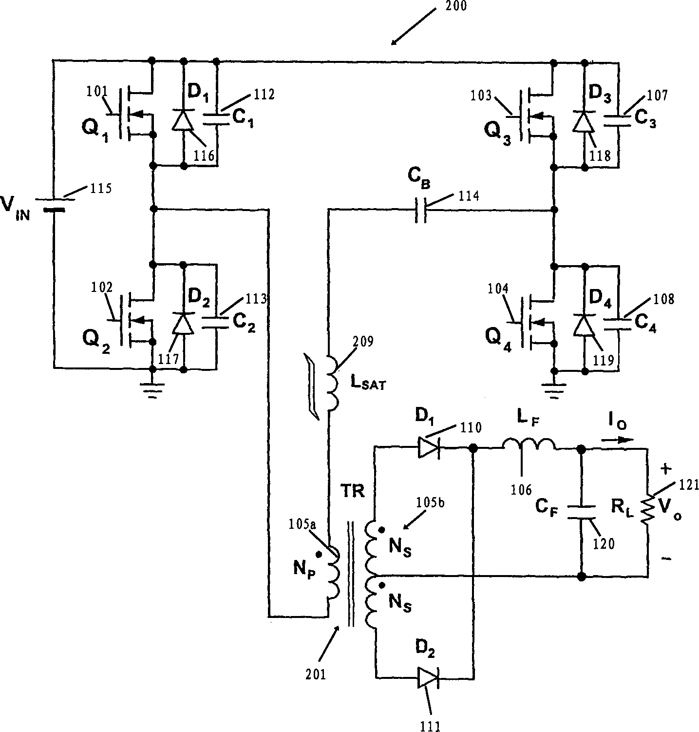
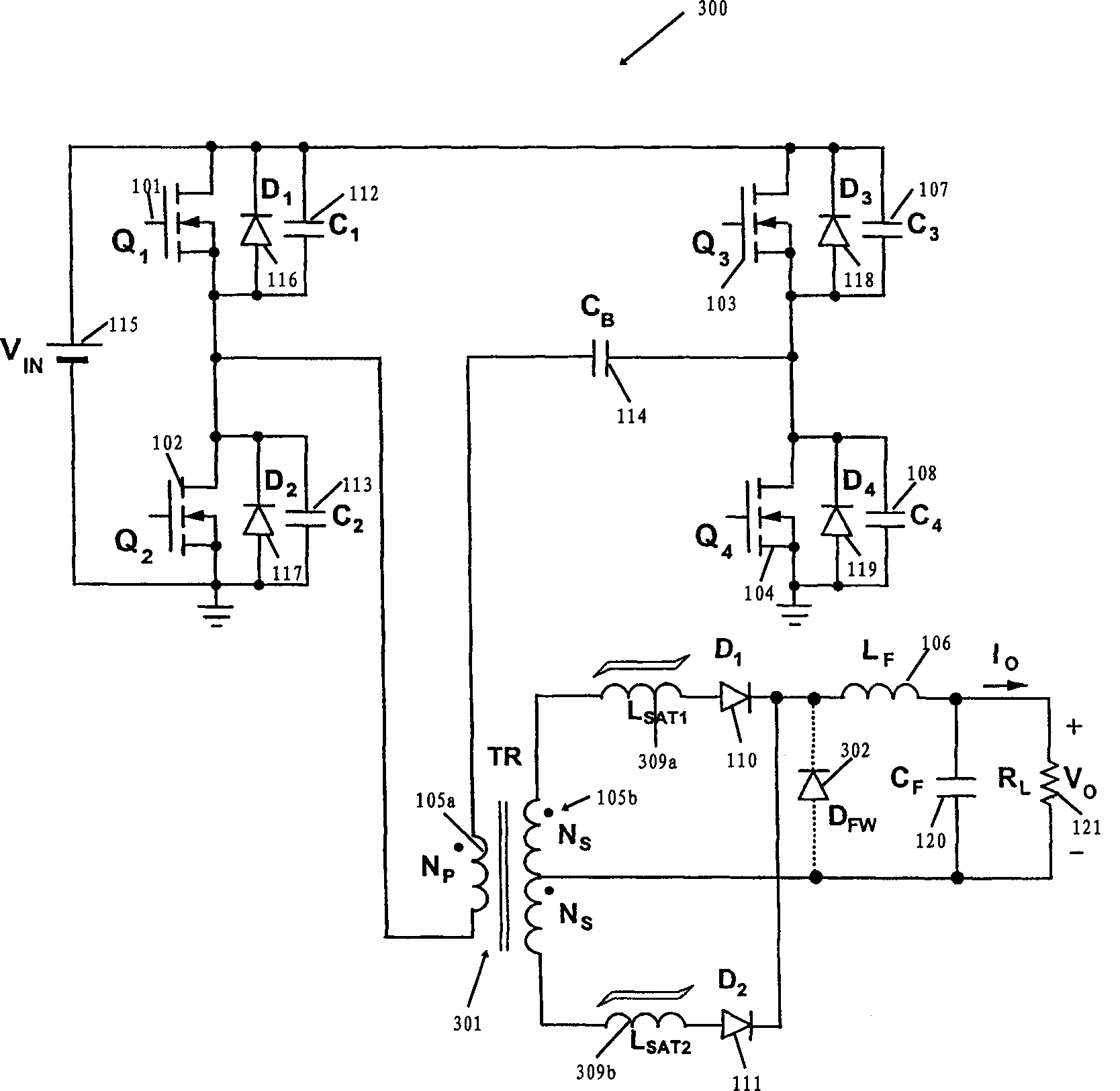
The soft switching completely bridging circuit pulse width modulation converter includes one coupling inductor to provide wide range ZVS state of input voltage and output load. In addition, the converter of the present invention needs neither leakage inductance of transformer nor outer inductor in realizing ZVS state.

Description

technical field [0001] The present invention relates to an isolated dc / dc converter. More particularly, the present invention relates to a constant frequency isolated dc / dc full-bridge converter which operates with zero voltage switching of the primary switches. Background technique [0002] Disadvantages affecting conventional "hard switching" pulse width modulation (PWM) converters at high switching frequencies are circuit parasitics such as semiconductor junction capacitance, transformer leakage inductance and rectifier reverse recovery. Typically, these parasitic effects introduce additional switching losses and increase component stress, thus limiting the maximum operating frequency of the converter. In order to operate the converter at high switching frequency and achieve a high power density, it is necessary to eliminate or reduce circuit parasitics without degrading the conversion efficiency. One method of incorporating circuit parasiti...

Claims


Application Information

Patent Timeline
Patent Type & Authority Applications(China)
IPC IPC(8): H02M3/335H02M7/48H02M7/487
CPCH02M3/33569Y02B70/10H02M1/0058H02M3/33573H02M3/01
Inventor 扬泰克·简米兰·M·乔瓦诺维克
Owner DELTA ELECTRONICS INC
Learn More