
Light beam deflector, exchange system, and method for coupling optical signal terminal

A beam deflection and incident beam technology, applied in the coupling of optical waveguides, optics, instruments, etc., can solve problems such as intensity loss, and achieve the effect of simple configuration

Inactive Publication Date: 2002-10-09
CARL ZEISS STIFTUNG
View PDF4 Cites 9 Cited by
  • Summary
  • Abstract
  • Description
  • Claims
  • Application Information

AI Technical Summary

Problems solved by technology

However, when the beam cycles through the resonator several times, the intrinsic absorption of the polymer material leads to a significant loss of intensity
In this way, dielectric absorption in the cavity limits the increase in the deflection angle

Method used


Image

  • Light beam deflector, exchange system, and method for coupling optical signal terminal
  • Light beam deflector, exchange system, and method for coupling optical signal terminal
  • Light beam deflector, exchange system, and method for coupling optical signal terminal

Examples


Embodiment Construction

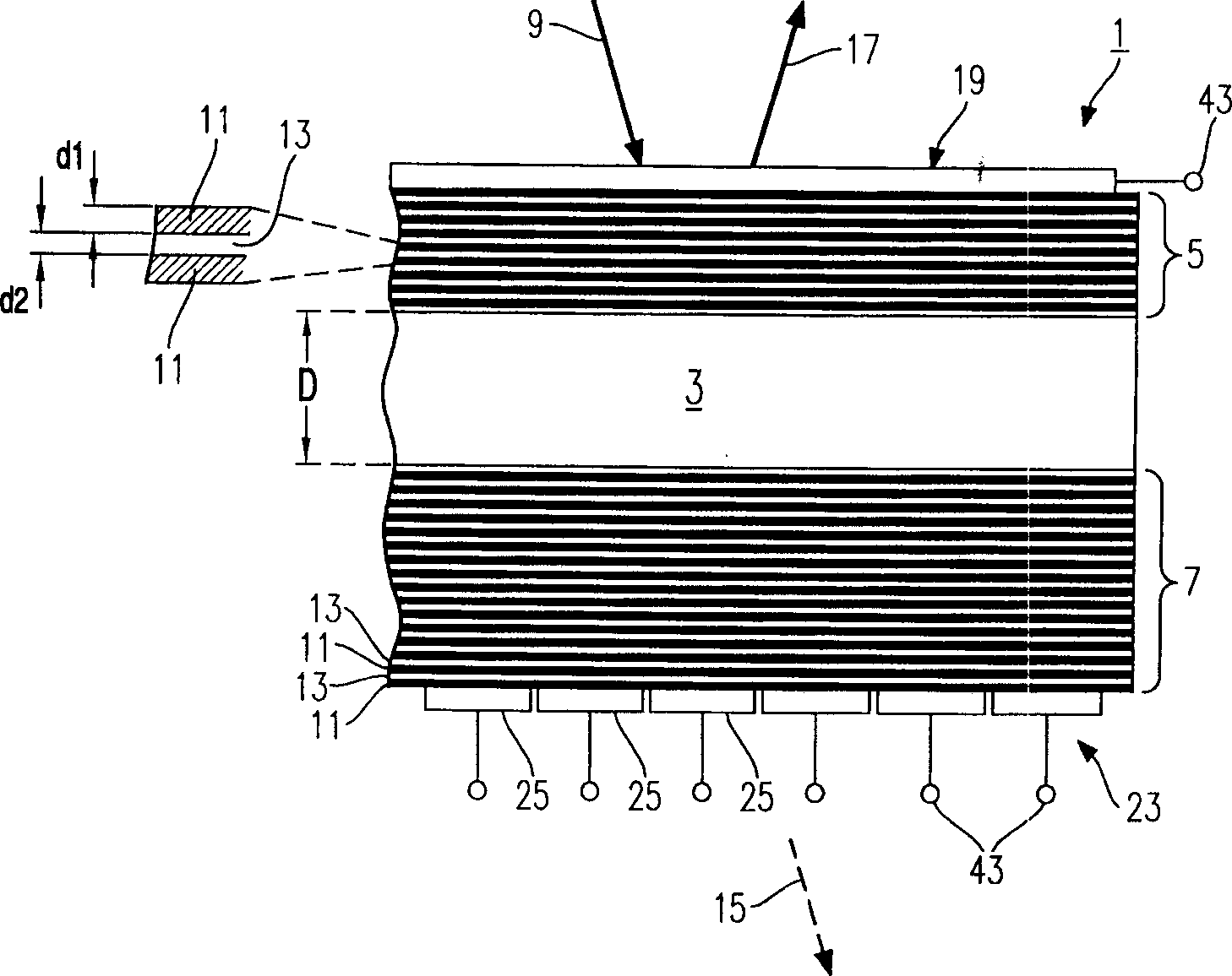
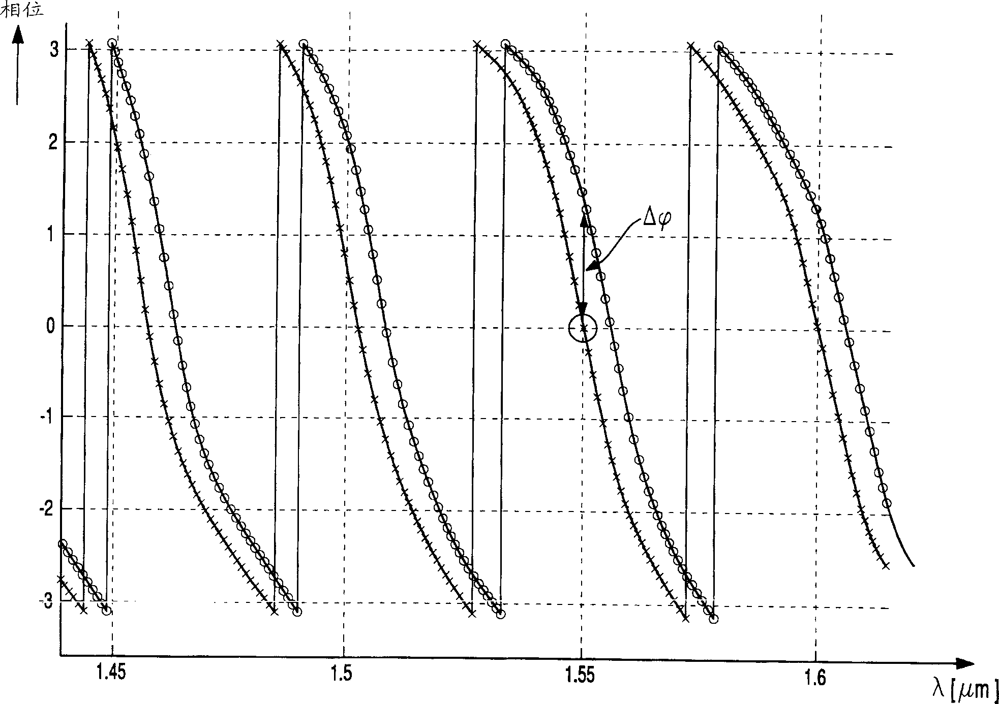
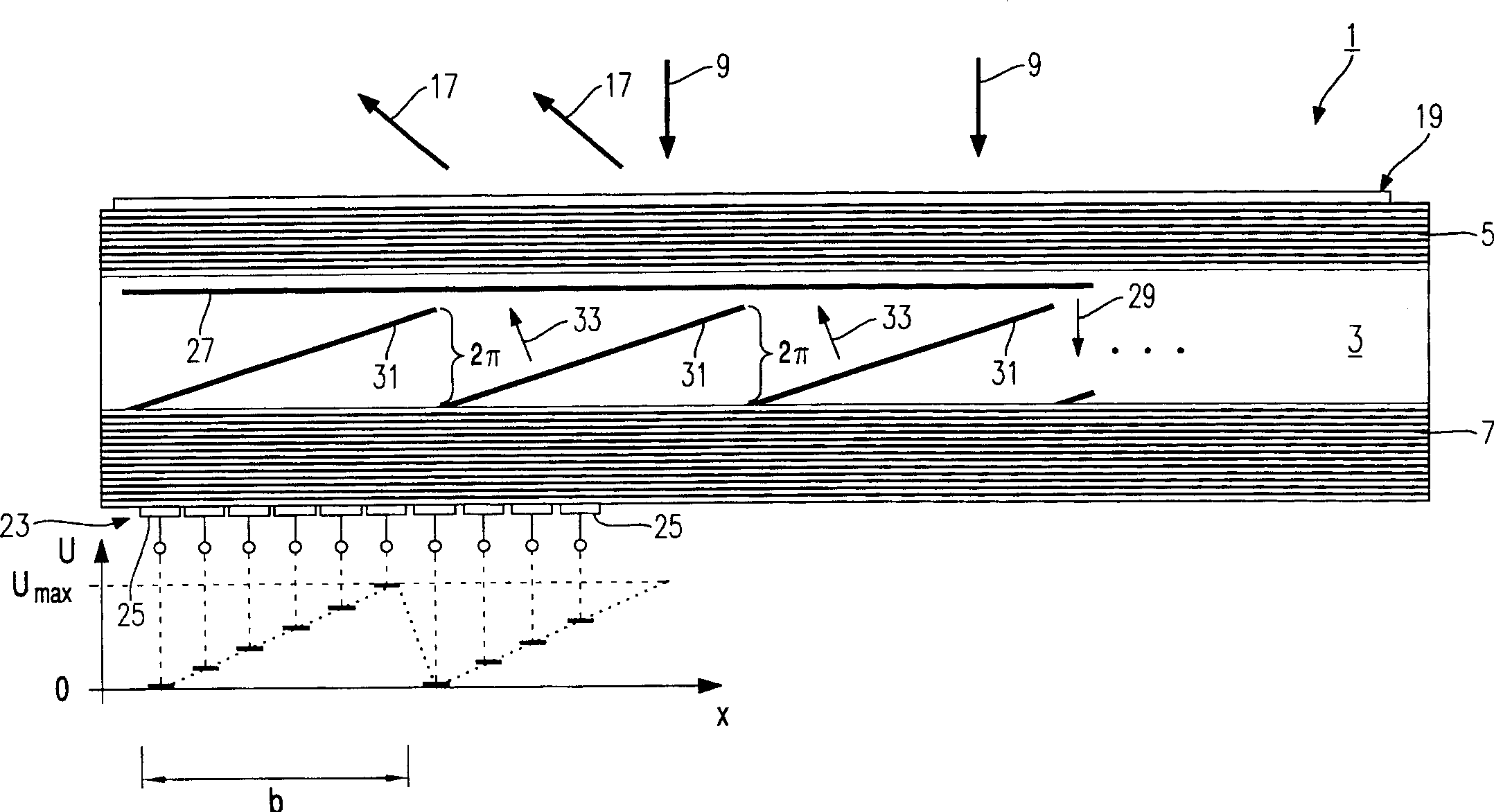
[0055] The following will refer to Figure 1 to Figure 4 , a first embodiment of the beam deflector 1 according to the invention will be described.

[0056] The structure of the beam deflector 1 is that of an optical resonator or etalon, in which a plate 3 of electro-optic material is arranged between two plane-parallel mirrors 5 and 7 . As mentioned herein, an electro-optic material refers to any material that has a significant (ie technically available) electro-optic effect, that is, the refractive index n of the electro-optic material can be changed by applying an electric field to the electro-optic material. For this reason, in particular, the so-called linear electro-optic effect of the applied electric field strength is what this paper focuses on.

[0057] The electro-optic material selected for this embodiment is lithium niobate (LiNbO 3 ), assuming that the refractive index of lithium niobate is n=2.3, the refractive index can be changed by Δn=5*10 by applying a suit...


PUM

PropertyMeasurementUnit
refractive indexaaaaaaaaaa

Abstract

A beam deflector for deflecting an incident beam (9) of light for a preset wavelength has a plate (3) of electrooptical material between two electrode structures (19,23) and first (5) and second (7) mirrors (5,7) plane-parallel to each other. The first mirror turned towards the incident beam of light has lower reflectivity than the second mirror. The first or second mirror can have multiple layers (11,13) of dielectric material each with a different refraction index. A Independent claim is also included for a connection method for use with multiple beam deflectors that has multiple connections for optical signals and connector ends for the entry / exit of optical signals as beams of light.

Description

field of invention [0001] The present invention relates to a beam deflector for deflecting a light beam in selectable directions, and a switching system comprising a plurality of optical signal terminals so that an optical signal entering the switching system through one or more terminals can be The other terminals selected are output. In particular, the invention also relates to a switching system for a data communication system with an optical fiber switching system. Moreover, the present invention also relates to a method for operating the switching system, in particular to a method for operating a fiber optic switching system. Background technique [0002] From the article written by B.H.Lee and R.J.Capik, entitled: "Demonstration of a very low-loss 576×576 servo-controlled, beam-steering optical switch structure" A light beam direction control switch is known in the optical switch fabric, and the light beam direction control switch can enable multiple optical fiber in...

Claims


Application Information

Patent Timeline
Patent Type & Authority Applications(China)
IPC IPC(8): G02F1/31G02F1/21G02F1/29
CPCG02F1/21G02F1/216G02F1/292G02F1/213
Inventor 凯·魏德利希
Owner CARL ZEISS STIFTUNG
Learn More