Method and equipment for positioning failure point of power transmission line

A transmission line and positioning device technology, applied in the direction of fault location, information technology support system, etc., can solve the problems of interference system control, protection and measurement, little necessity, complexity, etc., to improve sensitivity and positioning accuracy, anti-interference Effects of enhanced capabilities, simplified hardware and software

Inactive Publication Date: 2002-10-30
WUHAN NARI LIABILITY OF STATE GRID ELECTRIC POWER RES INST
View PDF1 Cites 17 Cited by
  • Summary
  • Abstract
  • Description
  • Claims
  • Application Information

AI Technical Summary

Problems solved by technology

There are several deficiencies in the existing technology: the signal is directly taken from CT or CVT, and the extracted signal contains power frequency components, which may interfere with the control, protection and measurement of the system; the high-frequency response characteristics of CT and CVT are not good. To accurately identify traveling wave signals, in addition to requiring high precision of CT, more complex hardware and software are required; it is not necessary to distinguish fault phases or fault forms, which can be achieved by fault recording and protection actions It can be judged according to the situation, and it can be directly judged when climbing the pole for emergency repair, so there is no need to complicate the fault location system for this

Method used


Image

  • Method and equipment for positioning failure point of power transmission line
  • Method and equipment for positioning failure point of power transmission line
  • Method and equipment for positioning failure point of power transmission line

Examples


Embodiment Construction

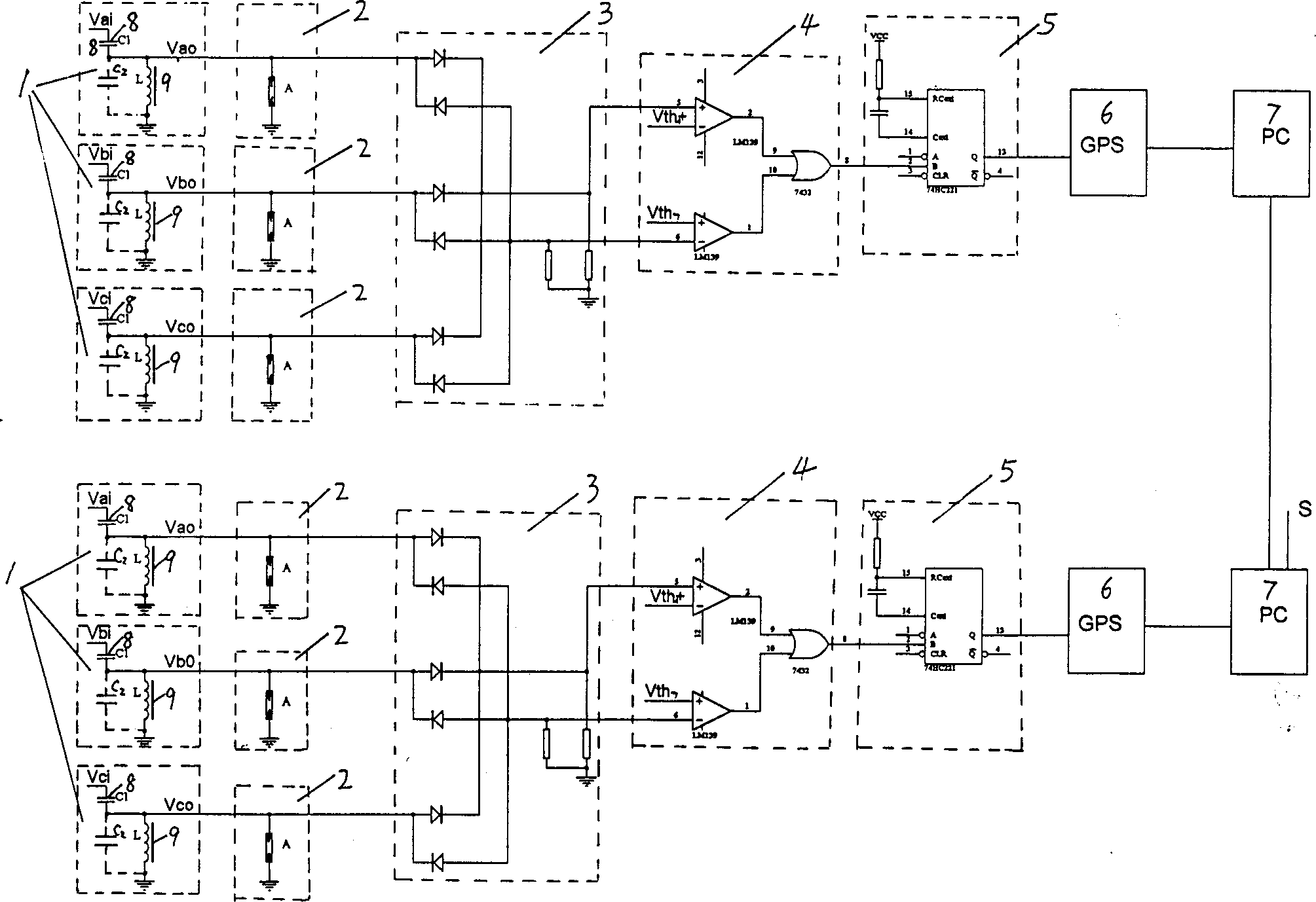
[0021] The present invention will be described in further detail below in conjunction with positive figure.

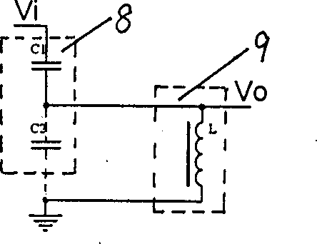
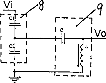
[0022] Such as figure 1 As shown, when the line under test fails, the fault traveling wave generated by the line fault is transmitted along the line to both sides at a speed close to the speed of light, and reaches the inherent capacitance equipment of the substation at both ends of the line, that is, the high voltage of the traveling wave signal extraction device 1. The arm capacitive element 8, such as the bushing capacitor of the main transformer or high-voltage electrical appliance, opens the original ground terminal of the capacitive element 8 and connects it to the small reactance 9 and then grounds it. Between the terminals, a distributed capacitance C2 will be generated between the capacitive element 8 of the high-voltage arm and the ground terminal; because the front edge of the fault waveform has a relatively large steepness and a high frequency, it can be sm...


PUM


Abstract

A method based on GPS and travelling wave method for locating the failure point of power transmission line features that a small reactor is serially connected with the capacitance element in transformer station and the failed travelling wave signal without industrial frequency interference is sampled from said small reactor. Its equipment is composed of travelling wave signal sampler, amplitude limiter, three-phase rectifier, threshold comparator, monostable trigger, GPS timing module and PC. Its advantages are wide application range, and high sensitivity, locating precision and anti-interference power.

Description

technical field [0001] The invention relates to the location of fault points of power transmission lines, in particular to a method and device for locating fault points of power transmission lines, and belongs to the technical field of power transmission equipment. Background technique [0002] At present, advanced transmission line fault location is based on GPS (Global Positioning System), and its principles include impedance method and traveling wave method. The impedance method is to use the voltage and current measured at the end of the line and the electrical parameters of the line itself to calculate the location of the fault point. The application number issued by the State Intellectual Property Office is 00124804.9 "Transmission Line Fault Point Location Method and Device" belongs to the impedance method , the main disadvantage of this method is that it is not easy to rule out the influence of line conductor transposition and the influence of geology and landform al...

Claims


Application Information

Patent Timeline
Patent Type & Authority Applications(China)
IPC IPC(8): G01R31/08
CPCY04S10/52
Inventor 吴维宁陈家宏张勤张文亮方玉河容健纲吴峡唐世宇王海涛冯万兴
Owner WUHAN NARI LIABILITY OF STATE GRID ELECTRIC POWER RES INST
Why Eureka
Try Eureka