Multi-zone resistance heater

A heater and heating element technology, which is applied in the direction of ohmic resistance heating, ohmic resistance heating parts, electric heating plate heating arrangement, etc., can solve the problem of difficult to isolate the temperature change of the chip

Inactive Publication Date: 2002-10-30
TOKYO ELECTRON LTD
View PDF0 Cites 20 Cited by
  • Summary
  • Abstract
  • Description
  • Claims
  • Application Information

AI Technical Summary

Problems solved by technology

Also, in known systems, radiative or lateral heat transfer is higher than in the substrate being processed, making it difficult to isolate temperature variations in the wafer

Method used


Image

  • Multi-zone resistance heater
  • Multi-zone resistance heater
  • Multi-zone resistance heater

Examples


no. 1 example

[0149] Although specific configurations and configurations of the resistive heating elements and cooling sections have been described, the actual configuration of the heating and cooling sections should be determined to match the thermal characteristics of the substrate being heated or cooled. According to a preferred first embodiment of the invention, the substrate to be processed having a certain shape and thickness is uniformly heated in an industrial furnace to the operating temperature to be heated on the chuck. The wafer to be heated is placed on the chuck, and a piece of liquid crystal display (LCD) paper is placed on the heated wafer because the color of the LCD paper changes with temperature. Take pictures of the LCD paper while cooling, observe / record the color of the LCD paper to observe / record the temperature change. The photo of the cooling process shows the opposite of the required heating of the substrate. That is, where heat loss is rapid, additional supplemen...


PUM


Abstract

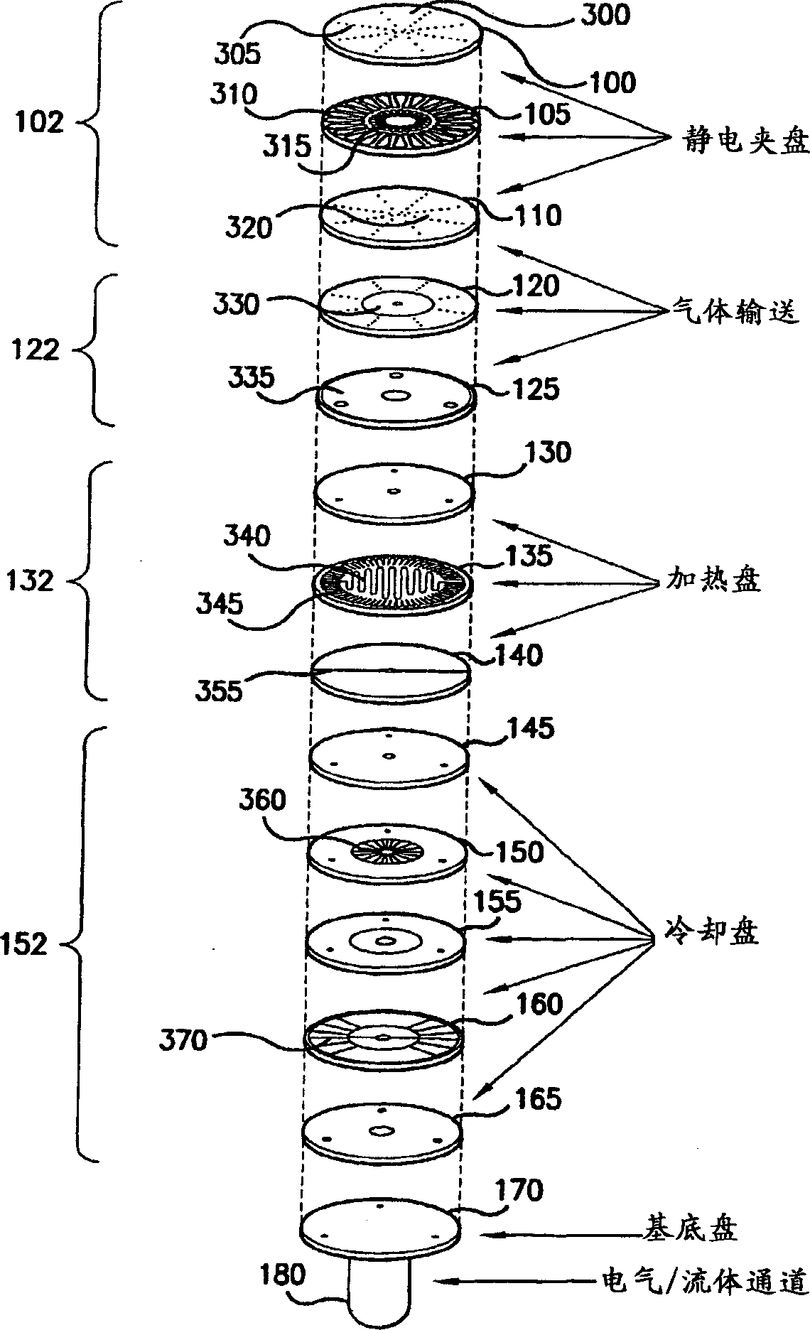
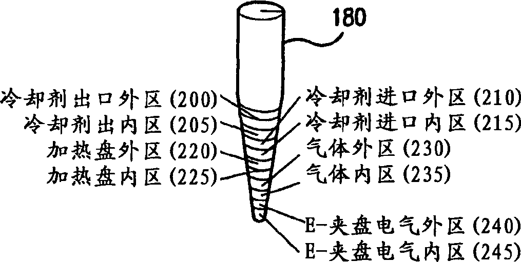
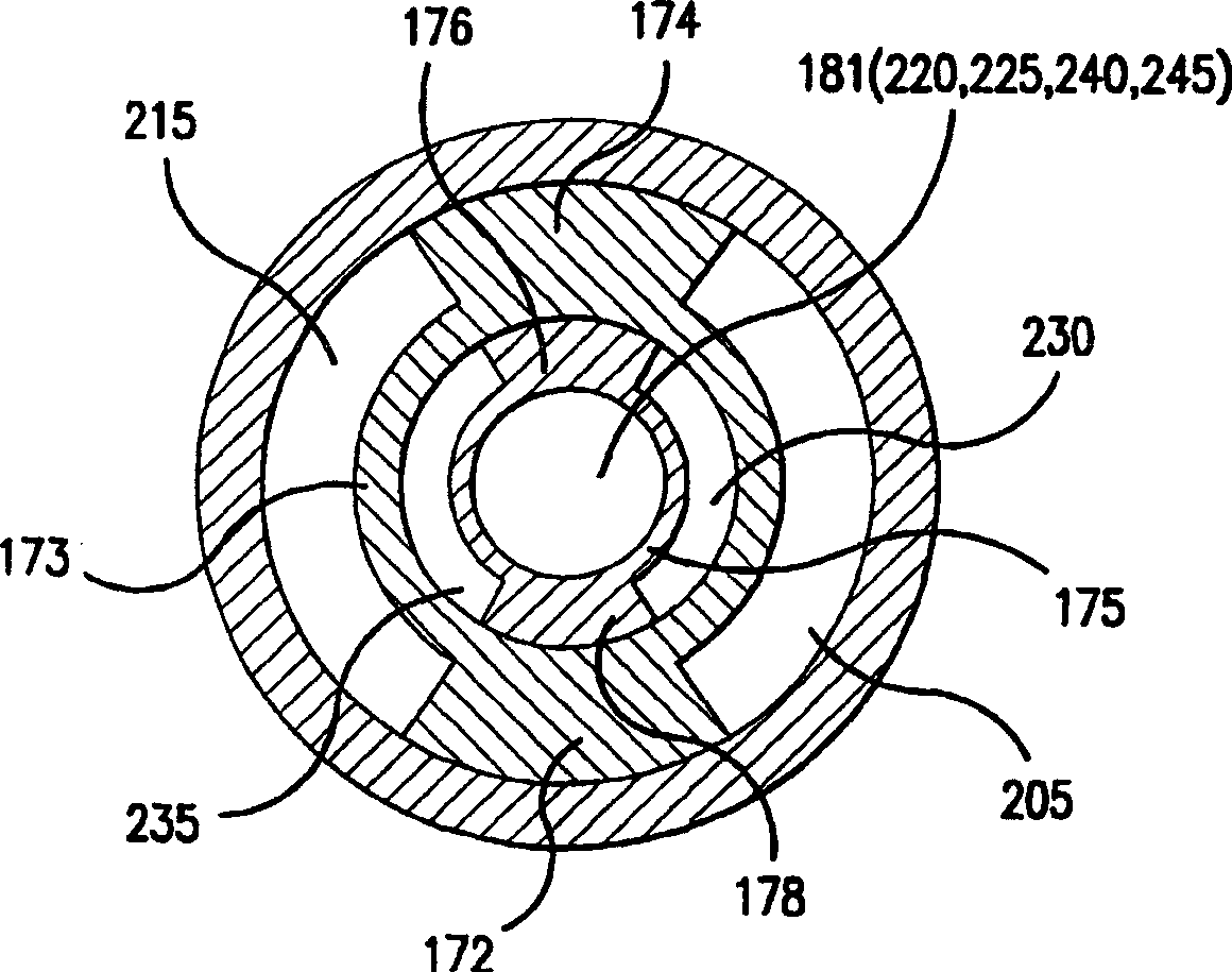
A substrate holder used to hold substrates (eg, wafers or liquid crystal panels) during plasma processing. The substrate holder is a stack of processing components, each component performing at least one function. The processing components include an electrostatic chuck (102), a helium delivery system (122), a multi-zone heating plate (132), and a multi-zone cooling system (152). Each component is designed to match the characteristics of the processing system, for example, using heat based on the heat loss characteristics of the substrate during normal processing. The overall design allows precise control of operating conditions including, but not limited to, rapid heating and rapid cooling of the substrate.

Description

[0001] Cross-Referenced Related Applications [0002] This application is related to and claims priority from application Serial No. 60 / 156595, filed September 29, 1999, the contents of which are incorporated herein by reference. technical field [0003] The present invention generally relates to a multipurpose wafer mount for holding wafers (or other substrates) during processing in a plasma system. In particular, the mount comprises at least one stacked layer for clamping, conduction, heating and / or cooling. Examples of these layers include electrostatic chucks, multi-zone helium delivery systems, multi-zone resistive heaters, and multi-zone cooling systems. Background technique [0004] It is known in the field of semiconductor processing to use resistive heaters to heat semiconductor wafers in the presence of process gases. Heating changes the characteristics of the reaction processes occurring in the semiconductor wafer. For example, such resistive heaters have been ...

Claims


Application Information

Patent Timeline
Patent Type & Authority Applications(China)
IPC IPC(8): H05B3/20C23C16/458C23C16/46H01L21/00H01L21/02H01L21/302H01L21/683H05B3/02H05B3/10
CPCC23C16/4586C23C16/46H01L21/67103H01L21/67109H01L21/6831H05B3/06
Inventor 威恩·L·约翰森埃里克·J·斯壮
Owner TOKYO ELECTRON LTD
Why Eureka
Try Eureka