Method and device for separating and recovering mercury

A technology for separation and recovery of mercury, applied in separation methods, distillation separation, chemical instruments and methods, etc., can solve problems such as thermal deterioration of phosphor powder, deterioration of brightness and other characteristics, and destruction of phosphor crystal structure

Inactive Publication Date: 2002-11-13
PANASONIC CORP
View PDF1 Cites 8 Cited by
  • Summary
  • Abstract
  • Description
  • Claims
  • Application Information

AI Technical Summary

Problems solved by technology

[0006] However, in the above-mentioned existing wet mercury separation and recovery method, there is a so-called part of the phosphor powder dissolved in the aqueous solution containing active sulfur, the crystal structure of the phosphor is destroyed and changed, and the properties such as brightness deteriorate, making it impossible to recycle. After the phosphor powder problem
[0007] In addition, in general, wet mercury separation and recovery methods also have the problem of requiring special equipment for waste water treatment of used aqueous solutions and higher recovery costs compared to dry mercury separation and recovery methods.
[0008] On the other hand, adopt existing dry use separation and recovery method, there is following problem, promptly when the mercury form that contains in phosphor powder is metallic mercury and oxidized mercury, can fully separate and recover mercury from phosphor powder, However, since the form of mercury contained in the phosphor powder in waste fluorescent lamps at the end of its life becomes an amalgam that reacts with emitters (electron emitting substances) and phosphor components, mercury is difficult to thermally decompose and cannot be removed from the phosphor powder. Fully separate and recover mercury
Therefore, although it is conceivable to raise the temperature during the heat treatment, in this case, the temperature during the heat treatment is too high, and the thermal deterioration of the phosphor powder is remarkable, and as a result, the characteristics such as brightness deteriorate, and it cannot be reused. Problems with Treated Phosphor Powders

Method used


Image

  • Method and device for separating and recovering mercury
  • Method and device for separating and recovering mercury
  • Method and device for separating and recovering mercury

Examples


no. 1 approach

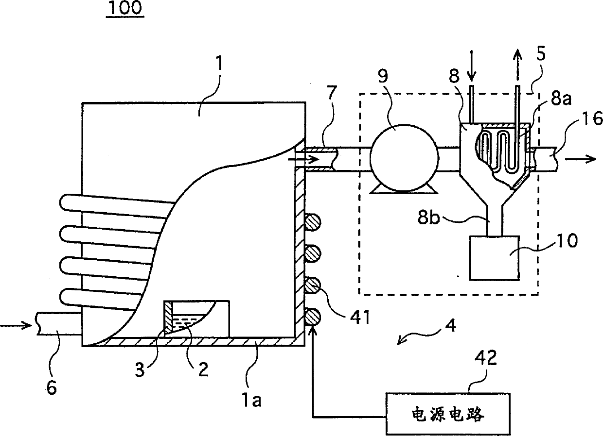
[0027] FIG. 1 is a structural diagram showing a mercury separation and recovery device 100 used in a mercury separation and recovery method according to a first embodiment of the present invention.

[0028] As shown in the same figure, this mercury separation and recovery device 100 is equipped with a cylindrical sealable metal reaction vessel 1, and the bottom of the reaction vessel 1 is arranged for containing phosphor powder containing mercury and A cylindrical distillation vessel 3 for the mixture 2 of the organic reducing agent, a heating device 4 for heating the mixture 2 in the distillation vessel 3 and vaporizing and separating mercury from the phosphor powder, and a reaction vessel 1 for absorbing and condensing Mercury Recovery of Vaporized Mercury Part 5.

[0029] The distillation vessel 3 is made of stainless steel and can be attached and detached from the bottom 1 a of the reaction vessel 1 . In addition, a pipeline 6 for feeding gases such as nitrogen and air is...

experiment example

[0049] The following will describe an experimental example for determining the effect of the method for separating and recovering mercury in the first embodiment.

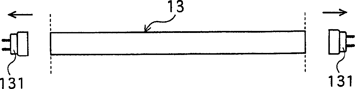
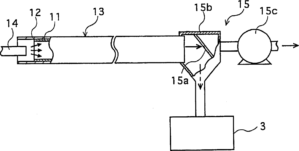
[0050] First, phosphor powder was recovered from the end-of-life straight-tube type waste fluorescent lamp 13 with a rated power of 40 W. The phosphor used in the waste fluorescent lamp 13 is made of red phosphor Y 2 o 3 : Eu, blue phosphor (SrCaBa) 5 (PO 4 ) 3 Cl:Eu, green phosphor LaPO 4 : Rare earth phosphor composed of Tb and Ce.

[0051] The amount of mercury contained in the recovered phosphor powder, that is, the phosphor powder before mercury separation (hereinafter referred to as "the phosphor powder before treatment") was 2800 μg per 2 g of the phosphor powder.

[0052] The phosphor powder before treatment was mixed into an aqueous solution in which oxalic acid was dissolved at a ratio of 0.4 g (20% by weight) of oxalic acid to 2 g of the phosphor powder to prepare a mixture A (Example 1).

[0053]...

no. 2 Embodiment approach

[0069] The following describes the mercury separation and recovery device related to the second embodiment of the present invention. Since this mercury separation and recovery device has the same structure as the mercury separation and recovery device 100 (FIG. 1) used in the mercury separation and recovery method in the first embodiment above, except that a spacer 17 made of a thermally conductive material is provided in the distillation vessel 3, structure, only the distillation vessel 3 will be described below.

[0070] Fig. 7A is a perspective view showing an example of the distillation vessel 3 in the second embodiment. As shown in the figure, a spacer member 17 composed of three stainless steel cylindrical members having different diameters is provided substantially concentrically in the distillation vessel 3 . 7B is a schematic diagram of heat conduction in the phosphor powder 20 in the distillation vessel 3 in the reaction vessel 1, and the distillation vessel 3 and t...


PUM


Abstract

The invention relates to a method and device for separating and recovering mercury. By cutting off both ends of a lamp tube of a waste fluorescent lamp and peeling off a phosphor film formed on the inner surface of the lamp tube, phosphor powder containing mercury is recovered. Adding an organic reducing agent to the recovered phosphor powder and heating it to perform dry heating reduction treatment to vaporize and separate mercury from the phosphor powder. This vaporized mercury is condensed and recovered.

Description

technical field [0001] The invention relates to a method for separating and recovering mercury and a device for separating and recovering mercury, in particular to a technique for separating and recovering mercury contained in a fluorescent material of a fluorescent lamp from a fluorescent material. Background technique [0002] Generally, mercury, a harmful substance, is recovered when disposing of end-of-life fluorescent lamps and defective fluorescent lamps generated during the manufacturing process, etc. (hereinafter referred to as "waste fluorescent lamps"). The recovered mercury is reused after removing impurities and the like contained therein. [0003] At present, as a method of separating and recovering mercury enclosed in waste fluorescent lamps, especially mercury contained in phosphor powders of waste fluorescent lamps, from phosphor powders (fluorescent substances), it is known that phosphor powders recovered from waste fluorescent lamps A wet mercury separatio...

Claims


Application Information

Patent Timeline
Patent Type & Authority Applications(China)
IPC IPC(8): B09B3/00B01D3/00B01D3/34B09B5/00C22B5/00C22B5/02C22B7/00C22B9/02C22B43/00
CPCC22B5/00C22B7/001C22B43/00Y02P10/20
Inventor 藤原健児藤浪清胜
Owner PANASONIC CORP
Why Eureka
Try Eureka