Pile-driving hydraulic hammer

A technology for piling engineering and hydraulic hammer, which is applied in infrastructure engineering, sheet pile walls, buildings, etc., and can solve problems such as environmental pollution

Inactive Publication Date: 2003-01-08
周荣珍
View PDF0 Cites 12 Cited by
  • Summary
  • Abstract
  • Description
  • Claims
  • Application Information

AI Technical Summary

Problems solved by technology

[0002] In the existing technology, piles must be driven in the construction of high-rise buildings and soft soil foundations, and diesel impact hammers have been used in previous piling projects. During pile

Method used


Image

  • Pile-driving hydraulic hammer
  • Pile-driving hydraulic hammer
  • Pile-driving hydraulic hammer

Examples


Embodiment 1

[0010] Embodiment 1 is the same.

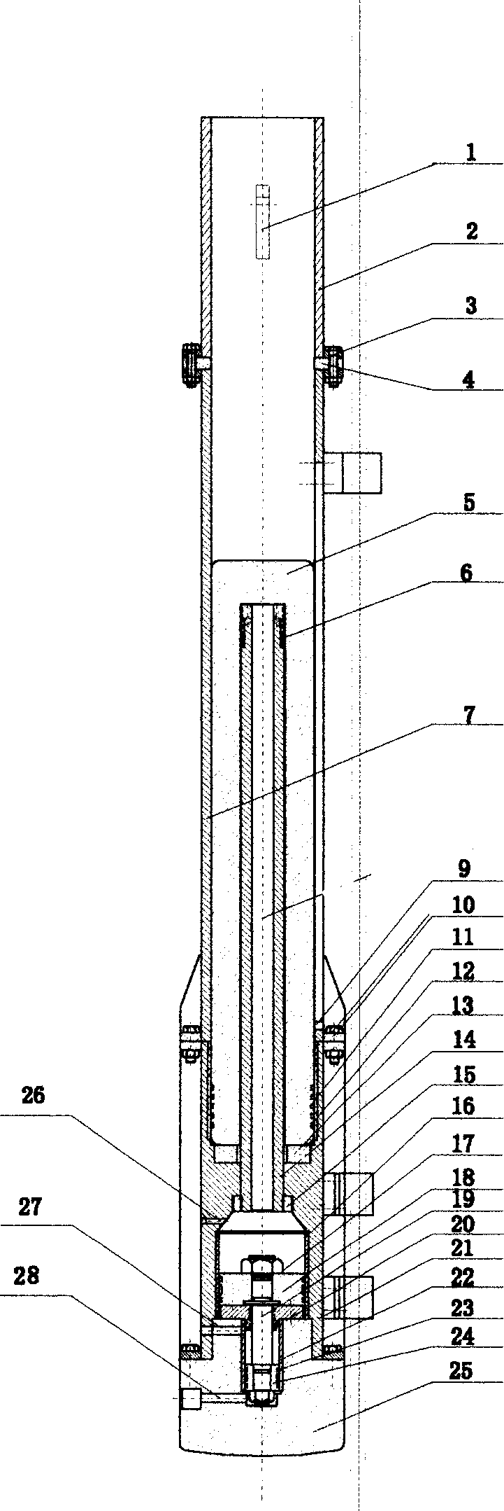
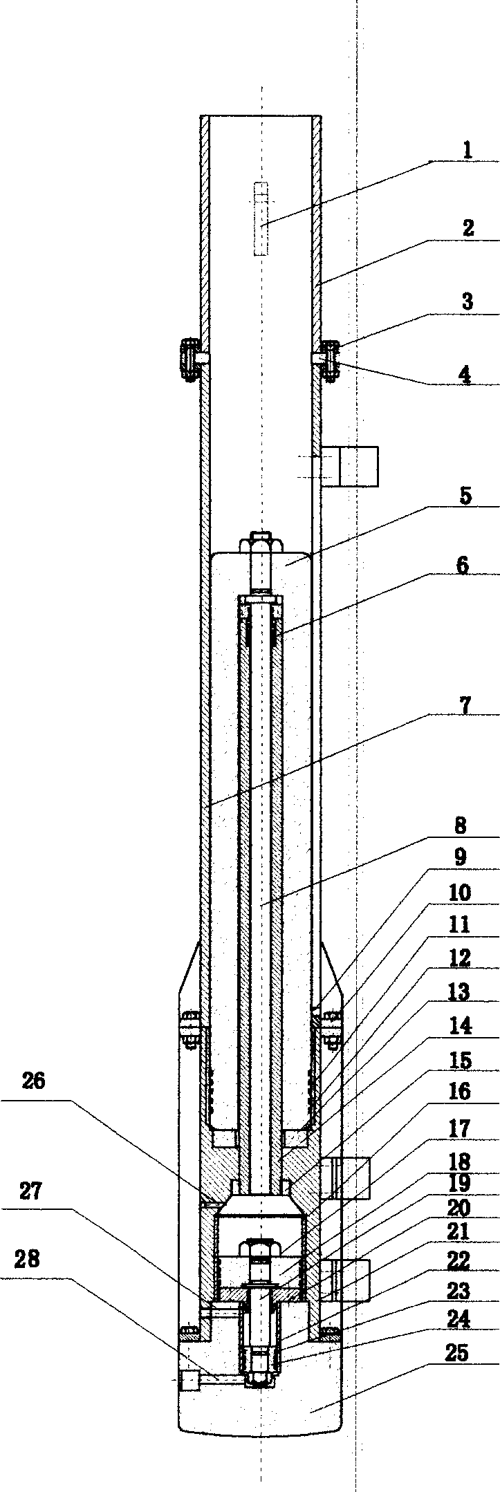
[0011] When the present invention works, turn on the starting switch, the electromagnetic valve works, the oil cylinder and the air cylinder of the hydraulic hammer are respectively connected with the external hydraulic source or air pressure source, the machine runs normally, the hydraulic source supplies oil to the oil cylinder 22 through the oil joint 28, and the oil When the pressure increases, the piston 24 is pushed upward, and the piston 24 drives the piston rod 19 and at the same time drives the upper piston 18 to spray the hydraulic oil in the oil cylinder 16 from the oil outlet to the inner long cylinder 14, forcing the piston cylinder hammer 5 to push upward, so that When the piston cylinder hammer 5 speeds up the movement speed to the design height, the solenoid valve switches the oil pressure source to supply oil to the oil cylinder 22 through the oil joint 27, so that the lower piston 24 in the oil cylinder 22 moves downward to d...


PUM


Abstract

It is a kind of piling work hydraulic pressure hammer. The main character lays on that, the hammer comprises oil chamber, air chamber and piston chamber hammer. The said air chamber is set on the oil chamber seat. The said piston chamber hammer is set in the outer long chamber. The said hydraulic pressure hammer, out-set liquid pressure source or air pressure source and electrical source get combined to use. When it works, because of the corporation of liquid or air pressure and electric system, the liquid spray through the oil chamber mouth from oil chamber, that propel the pistol chamber to go up, according to the freedom dropping theory, the air is pressed in the air chamber that make the pistol chamber hammer to press the pile-head to produce piling.

Description

technical field [0001] The invention relates to an improved invention of a construction machinery piling hammer, in particular to an invention of a piling hydraulic hammer. Background technique [0002] In the prior art, piles must be driven in the construction of high-rise buildings and soft soil foundations, and diesel impact hammers have been used in previous piling projects. During pile driving in infrastructure, the noise and exhaust gas of diesel impact hammers have caused serious environmental pollution. The nearby residents, institutions, schools and construction teams are very troubled. Contents of the invention [0003] In view of the problems existing in the known technology, the object of the present invention is to provide a piling hammer with scientific structure, easy operation, complete and effective reduction of noise and elimination of exhaust gas, and protection of the urban environment. The key to eliminating nois...

Claims


Application Information

Patent Timeline
IPC IPC(8): E02D7/10
Inventor 周荣珍
Owner 周荣珍
Why Eureka
Try Eureka