Improved wide-band erbium-mixed optical-fiber amplifier

A fiber amplifier and amplifier technology, applied in the field of optical communication systems, can solve problems such as inability to accurately monitor optical power

Inactive Publication Date: 2003-01-08
SAMSUNG ELECTRONICS CO LTD
View PDF0 Cites 8 Cited by
  • Summary
  • Abstract
  • Description
  • Claims
  • Application Information

AI Technical Summary

Problems solved by technology

In the case of providing multiple repeaters each containing an optical amplifier in a fiber optic transmission line, the ASE of the noise spectru

Method used


Image

  • Improved wide-band erbium-mixed optical-fiber amplifier
  • Improved wide-band erbium-mixed optical-fiber amplifier
  • Improved wide-band erbium-mixed optical-fiber amplifier

Examples


Embodiment Construction

[0016] In the following description, for purposes of illustration rather than limitation, specific details are given, such as specific structures, interfaces, techniques, etc., in order to provide a thorough understanding of the present invention. It will be apparent, however, to one skilled in the art that the present invention may be practiced in embodiments other than these specific details. For purposes of simplicity and clarity, detailed descriptions of well-known devices and methods are omitted so as not to obscure the present invention in unnecessary detail.

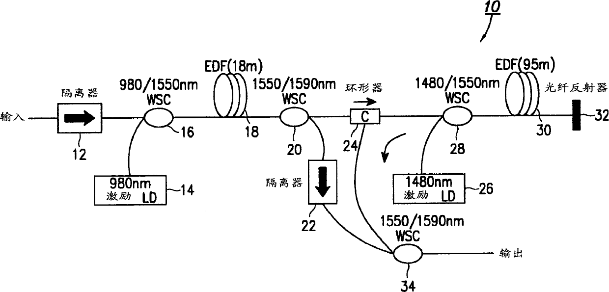
[0017] Fig. 3 shows a broadband optical amplifier 10 according to a first embodiment of the invention. The amplifier 10 of the present invention is divided into two amplifier parts, a first-stage amplifier formed by a first EDF 18 excited by a 980nm excitation laser diode (LD) 14, and a second EDF 30 excited by a 1480nm excitation laser diode (LD) 26 the first stage amplifier. The amplifier 10 of the present inv...


PUM


Abstract

An optical amplifier with improved output power utilizing less optical fiber components and reduced noise is disclosed. A first optical fiber amplifier is pumped by a first light source prior to splitting into a number of sub-bands, and a second optical fiber amplifier is pumped by a second light source. One of the sub-bands is amplified in multiple stages using a reflector, by passing the amplified sub-band back into the second optical amplifier in a reverse direction. Thereafter, all amplified sub-band signals are recombined to produce an output signal.

Description

technical field [0001] The present invention relates to optical communication systems, and more particularly, to broadband optical amplifiers. Background technique [0002] In recent years, erbium-doped fiber amplifiers (EDFAs) capable of being used in optical communication systems have been put into practical use. For example, a plurality of optical signals each having a different wavelength are multiplexed together into wavelength division multiplexed (WDM) signal light. The wide wavelength band of the optical amplifier enables each of wavelength division multiplexed (WDM) signal lights to be amplified. In systems using EDFAs, the channel density has been limited by the available gain bandwidth of the EDFA. Therefore, increasing the gain bandwidth of the EDFA can increase the system capacity while maintaining the channel spacing and the bit rate of each channel. [0003] For wavelength division multiplexing (WDM) transmission systems, many different t...

Claims


Application Information

Patent Timeline
IPC IPC(8): H01S3/10G02B6/00H01S3/06H01S3/067H04B10/17H04B10/18
CPCH01S2301/02H04B10/2537H01S3/06758H04B10/2935H01S3/2333H01S3/0064G02B6/00
Inventor 宋宽雄黄星泽
Owner SAMSUNG ELECTRONICS CO LTD
Why Eureka
Try Eureka