

Lithium accumulator with improved negative pole structure and its preparing method
A lithium storage battery and storage battery technology, which can be applied to lithium storage batteries, non-aqueous electrolyte storage batteries, electrodes of non-aqueous electrolyte storage batteries, etc., can solve problems such as instability of lithium metal
- Summary
- Abstract
- Description
- Claims
- Application Information
AI Technical Summary
Problems solved by technology
Method used
Image

Examples
preparation example Construction
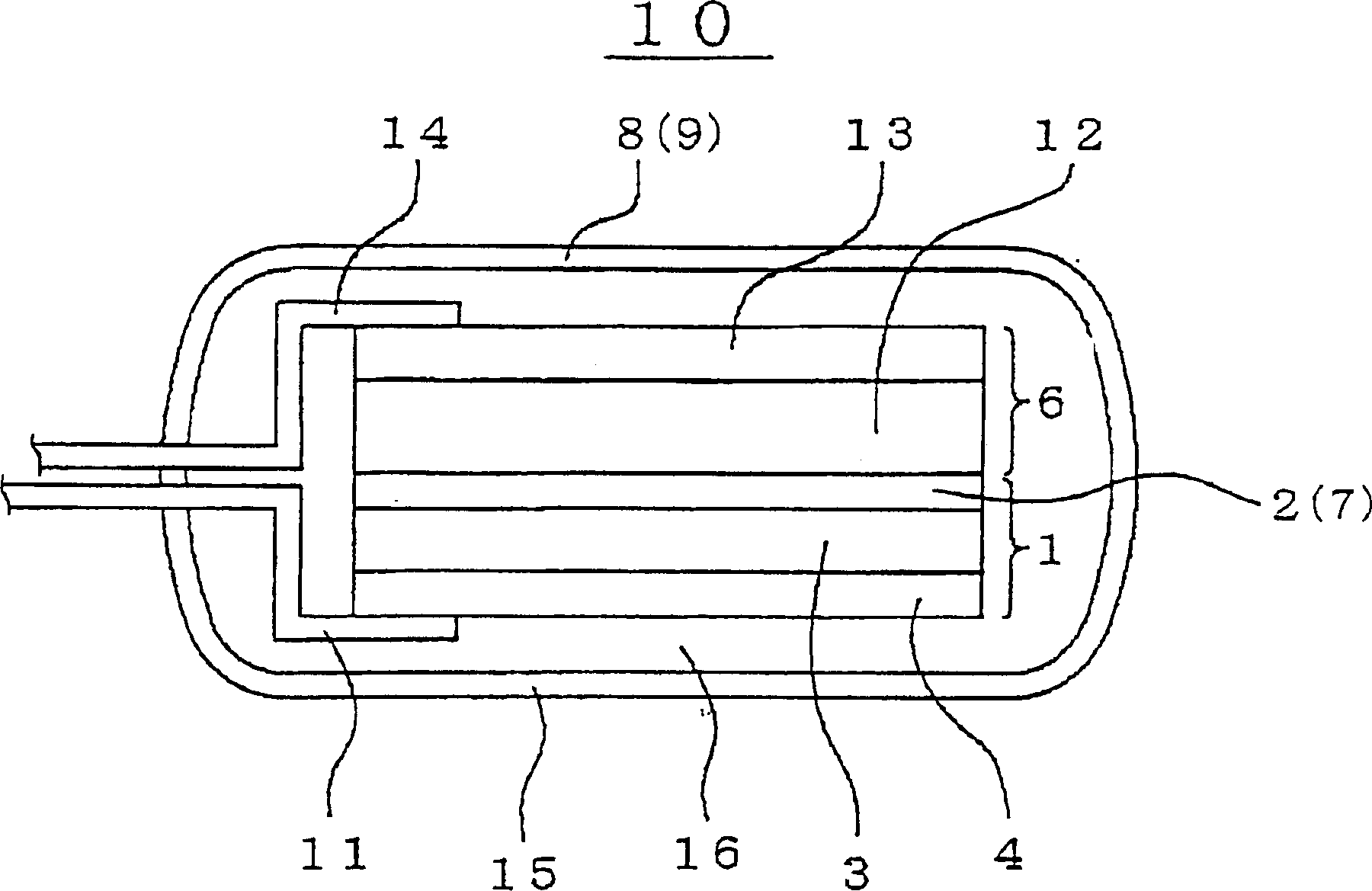
[0078] The positive electrode 6 can be prepared by applying a mixture of composite oxide, conductive material, binder and solvent to the substrate or base layer. Composite oxides can generally use Li x MO 2 where "M" represents at least one transition metal. For example, a preferred example of composite oxides may be Li x CoO 2 , Li x NiO 2 , Li x mn 2 o 4 , Li x MnO 3 and Li x Ni y C 1-y o 2 . A preferred example of the conductive material may generally be carbon black. An example of a preferred binder may be PVDF. An example of a preferred solvent is N-methyl-2-pyrrolidone (NMP). A preferred example of a substrate or base layer may be aluminum foil.
[0079] If an additional separator 7 is inserted between the negative electrode 1 and the positive electrode 6, the separator 7 may optionally and preferably include one selected from various polyolefins such as polyethylene and polypropylene porous films and fluororesins. In negative electrode 1, lithium ion ...
Embodiment 1
[0084] A preferred example of the method of manufacturing the lithium secondary battery of the present invention will be described in more detail below. Example 1 : (formation of negative electrode 1)
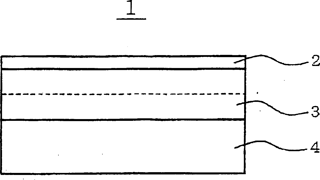
[0085] A lithium ion supporting layer 2 is prepared, which includes a square polyethylene porous membrane of 50 mm×50 mm and 10 μm thick. The lithium ion supporting layer 2 is placed in the chamber of the vacuum evaporation system as a matrix. The indoor pressure of the vacuum evaporation system is reduced to a vacuum degree of 1E-5Pa. In order to form an amorphous lithium metal layer 3 with a thickness of 2 μm on the lithium ion supporting layer 2 to form the first lamination structure, lithium is evaporated by irradiation with electron beams.
[0086] In the same manner as above, a lithium-evaporated layer 3' was formed on the current collector 4 (including copper foil) by resistance heating, thereby forming a second lamination structure.
[0087] The first and second lam...
Embodiment 2
[0103] A lithium secondary battery was prepared in the same manner as in Example 1 above, except that the lithium ion support layer 2 contained lithium fluoride (LiF) instead of polyethylene. The average cycle efficiency E (%) of the lithium storage battery in Example 2 is 98.5%, which is higher than that of Example 1. The polyethylene porous membrane lithium ion support layer 2 in direct contact with the amorphous lithium metal or alloy layer 3 can support lithium ions and ensure the required high uniformity of lithium ions on the surface of the lithium metal or alloy layer 3 . This high uniformity of Li ions on the Li metal or alloy surface prevents any Li partial discharge or any dendrite growth, resulting in increased cycle life or improved cycle characteristics. Comparative example 2 :
PUM
| Property | Measurement | Unit |
|---|---|---|
| Thickness | aaaaa | aaaaa |
| Thickness | aaaaa | aaaaa |
Abstract
Description
Claims
Application Information