Flue gas desulfurizing process for heat and power boler

A technology of boiler flue gas and desulfurization process, which is applied to the separation of dispersed particles, chemical instruments and methods, and separation methods, etc. It can solve the problems of secondary pollution, water in the exhaust gas, and easy scaling of the desulfurization system, so as to achieve the goal of not being easily blocked , to ensure the effect of the spray effect

Inactive Publication Date: 2003-03-12
济南市环境保护高新技术开发公司
View PDF0 Cites 5 Cited by
  • Summary
  • Abstract
  • Description
  • Claims
  • Application Information

AI Technical Summary

Problems solved by technology

[0007] The invention provides a flue gas desulfurization process of a thermoelectric boiler, which can solve the problems existing in the prior art that the desulfurization product is unsta

Method used


Image

  • Flue gas desulfurizing process for heat and power boler
  • Flue gas desulfurizing process for heat and power boler
  • Flue gas desulfurizing process for heat and power boler

Examples


Embodiment Construction

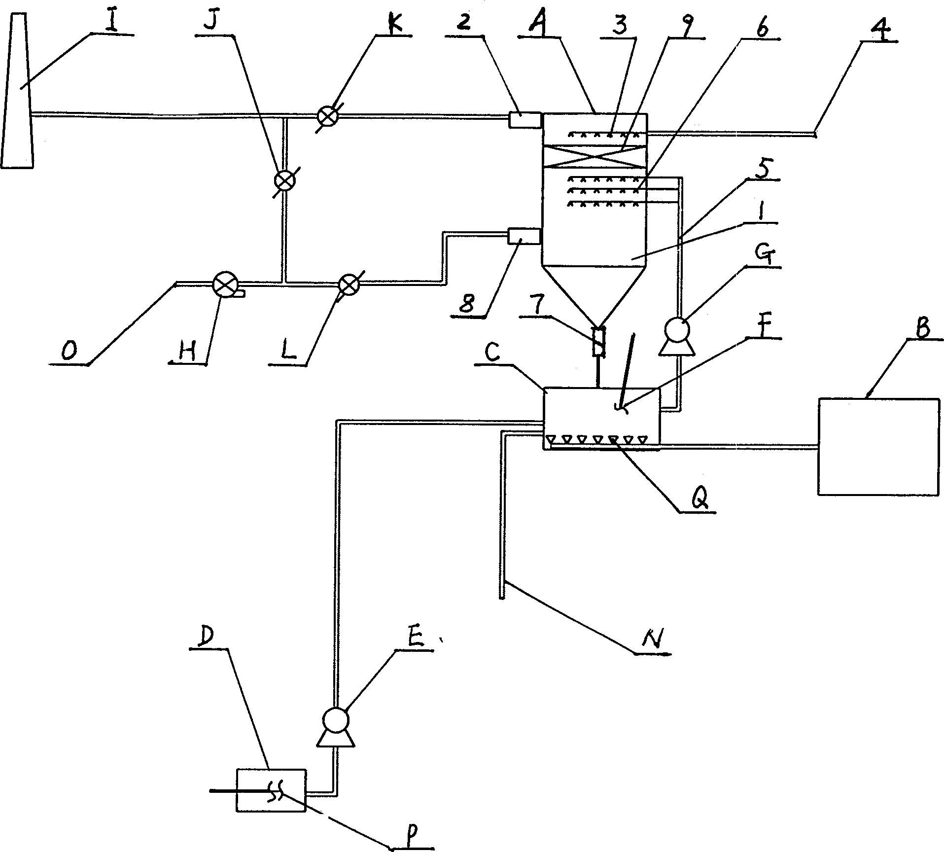
[0018] Flue gas desulfurization process of thermoelectric boiler: Lime slurry tank D sends the absorption liquid into circulation tank C through feed pump E, and the flue gas after dust removal is sent to desulfurization tower A by fan H through the flue inlet O, and the circulation tank The absorption liquid in C is atomized and sprayed into the desulfurization tower A through the circulation pump G, and the flue gas and the absorption liquid fully contact and react to form CaSO 3 .1 / 2H 2 O The mixed liquid enters the circulation tank C from the bottom of the absorption tower A, and when the oxygenator B aerates the gas distribution pipe Q in the circulation tank C, the mixed liquid is oxidized to form gypsum crystals, and the circulation pump G makes the absorption liquid flow between the desulfurization tower A and the The reciprocating circulation between the circulation tanks C, the gypsum crystal slurry is discharged through the slurry discharge pipe N; the smoke with wa...


PUM


Abstract

A process for desulfurizing flue gas of the boiler in steam-power plant is characterized by that after dusted the flue gas is blown into desulfurizing tower, where it reacts with the absorption liquid sprayed by circulating pump from tank into said tower to produce CaSO3.1/2H2O liquid, the air is filled by aerator into said CaSO3.1/2H2O liquid for oxidizing it to obtain gypsum crystal to be discharged, and the resultant flue gas is demisted for exhausting it via chimney. Its advantages are no secondary pollution, and high effect.

Description

technical field [0001] The invention relates to the technical field of flue gas desulfurization of thermal electric boilers. Background technique [0002] At present, the flue gas desulfurization process of thermoelectric boilers widely used in industry, especially the wet desulfurization process, has the following disadvantages in specific applications: [0003] 1. There is no oxygenation device, which leads to unstable desulfurization products and easy to cause secondary pollution. In the traditional desulfurization process, the final product is SO 3 2- Compounds, easy to precipitate SO in the wind, rain, and exposure environments 2 or form H 2 SO 3 , re-entering the air or flowing into the sewer ditch will cause secondary pollution. [0004] Second, the problem of water in the exhaust flue gas is serious. Most of the traditional dehydration and defogging devices adopt steel ball net structure, which is easily blocked by smoke and dust, resulting in large resistance...

Claims


Application Information

Patent Timeline
IPC IPC(8): B01D53/50B01D53/78
Inventor 张战朝陈雷雷
Owner 济南市环境保护高新技术开发公司
Why Eureka
Try Eureka