Rolling artificial knee joint

An artificial knee joint, rolling technology, applied in the direction of knee joint, elbow joint, joint implant, etc., can solve the problems of long-term failure of prosthesis, large amount of wear, low friction coefficient, etc., to avoid biological toxicity, Considerable economic benefits, obvious social benefits and effects

Inactive Publication Date: 2003-03-19
SHANGHAI SIXTH PEOPLES HOSPITAL +1
View PDF0 Cites 4 Cited by
  • Summary
  • Abstract
  • Description
  • Claims
  • Application Information

AI Technical Summary

Problems solved by technology

The defects of these artificial knee joints are: (1) in order to reduce the friction coefficient between the femoro-tibial articular surfaces, artificial knee joints mostly adopt ultra-high molecular weight polyethylene and metal with low friction coefficient as the friction pair
However, ultra-high molecular weight polyethylene has a large amount of wear and tear, which can easily lead to long-term failure of the prosthesis
Moreover, the severe osteolysis caused by the abrasive particles will lead to a high loosening rate of the prosthesis in the medium and long term, which will shorten the service life of the artificial joint.
(2) The restrictive prosthesis is limited to a single plane of movement, which can easily cause abnormal concentration of stress at the prosthesis-bone cement-bone tissue interface
The flat polyethylene platform has a small degree of knee joint activity, but because the tibiofemoral joint is in point contact when the knee is flexed, the local compressive stress load is greatly increased, which aggravates the wear of polyethylene and affects its service life
If the articular surface of the polyethylene platform is cup-shaped and the curvature matches the shape of the femoral condyle, increasing the contact of the tibiofemoral articular surface can reduce the compressive stress load per unit area of ​​the joint, but this design also limits joint motion, especially Rotational movement, causing the interface stress of prosthesis-bone cement-bone tissue to increase
After literature search, it was found that H.ThabeBad Kreuznach.Germany wrote an article "Mobile Bearing Total Knee Arthroplasty (Mobile Meniscal Type Total Knee Arthroplasty) in "Proceedings of the Seventh World Artificial Joint Academic Association and International Symposium" p112-115 )”, this paper proposes a design concept of a movable meniscus type artificial knee joint, which is used to solve the contradiction between the matching between the articular surfaces and the range of motion of the joint. However, due to the extremely strict requirements for medical implant materials, it is extremely difficult to improve and obtain approval of materials, and it still cannot avoid the problem of polyethylene wear. In addition, this artificial knee joint also increases A new wear area is the wear between the substrate and the mobile meniscus of polyethylene

Method used


Image

  • Rolling artificial knee joint
  • Rolling artificial knee joint
  • Rolling artificial knee joint

Examples


Embodiment Construction

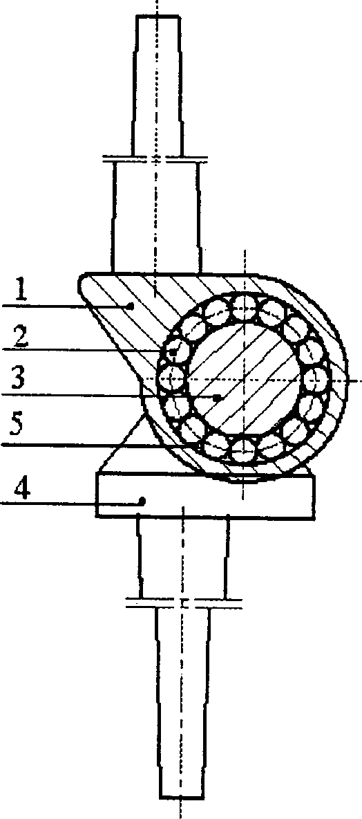
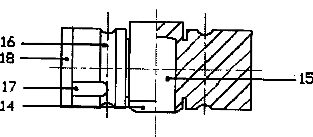
[0015] Such as figure 1 , figure 2 , image 3 , Figure 4 As shown, the present invention mainly includes: femoral component 1, rolling element 2, mandrel 3, and tibial component 4. The connection method is: femoral component 1 and mandrel 3 have two raceways 12 and 16, corresponding to raceways. Combine to form two annular spaces 5 with a circular cross-section, the rolling element 2 is arranged in the annular space 6, the cylindrical protrusion 19 of the tibial component 4 is connected to the concave hole 15 of the spindle 3, and the spindle 3 is in the femoral component In the medial and lateral condyles 11 of 1, the femoral component 1, the rolling element 2, and the mandrel 3 form a structure equivalent to two rolling bearings.

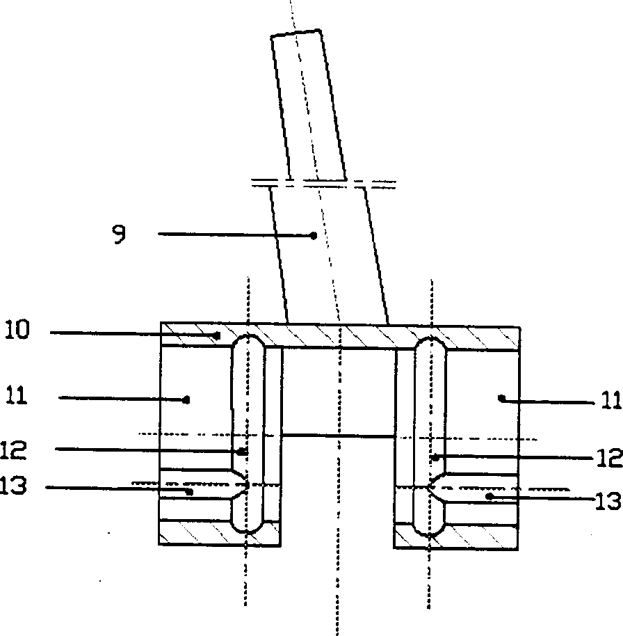
[0016] Femoral component 1 includes: intramedullary shaft 9, femoral platform 10, internal and external condyle 11, raceway 12, ball-loading gap 13, and its connection method is: except for intramedullary shaft 9, each part of femoral component 1 is...


PUM


Abstract

The present invention belongs to the field of artificial joint. The rolling artificial knee joint includes thigh part, roller, spindle and tibia part. The connection mode includes via the two roller tracks in the thigh part and the two roller tracks in the spindle to form one ring space, setting the roller in the ring space, connecting the libia part and the spindle, setting the spindle in the internal and external condyles and forming two rolling bearing-like structures with the thigh part, roller and spindle. The present invention has reduced prosthesis wear, prolonged use period, low production cost and no biological toxic action of polyethylene and can meet the treatment requirement of patient.

Description

Technical field [0001] The invention relates to an artificial knee joint, particularly a rolling artificial knee joint, which belongs to the field of artificial joints. Background technique [0002] The existing basic structure of artificial knee joints has three kinds of prostheses: restrictive, semi-restrictive and non-restrictive. Their structures are different, but the articular surface between the femur and tibia adopts a sliding friction method. The shortcomings of these artificial knee joints are: (1) In order to reduce the friction coefficient between the femoral and tibial joint surfaces, artificial knee joints mostly use ultra-high molecular weight polyethylene with low friction coefficient and metal as the friction pair. However, UHMWPE has a large amount of wear, which easily leads to long-term failure of the prosthesis. In addition, the severe osteolysis caused by its abrasive particles leads to a high rate of middle and long-term loosening of the prosthesis, which s...

Claims


Application Information

Patent Timeline
Patent Type & Authority Applications(China)
IPC IPC(8): A61F2/38A61F2/64
CPCA61F2002/30639A61F2/38
Inventor 于仲嘉王成焘
Owner SHANGHAI SIXTH PEOPLES HOSPITAL
Why Eureka
Try Eureka