
Manufacture of heat pipe for heat dissipating plate

A manufacturing method and heat dissipation plate technology, applied in the direction of electrical components, electric solid devices, circuits, etc., can solve the problems of difficult heat conduction, cracks, burning, etc.

Inactive Publication Date: 2003-06-04
HONG MANG
View PDF0 Cites 2 Cited by
  • Summary
  • Abstract
  • Description
  • Claims
  • Application Information

AI Technical Summary

Problems solved by technology

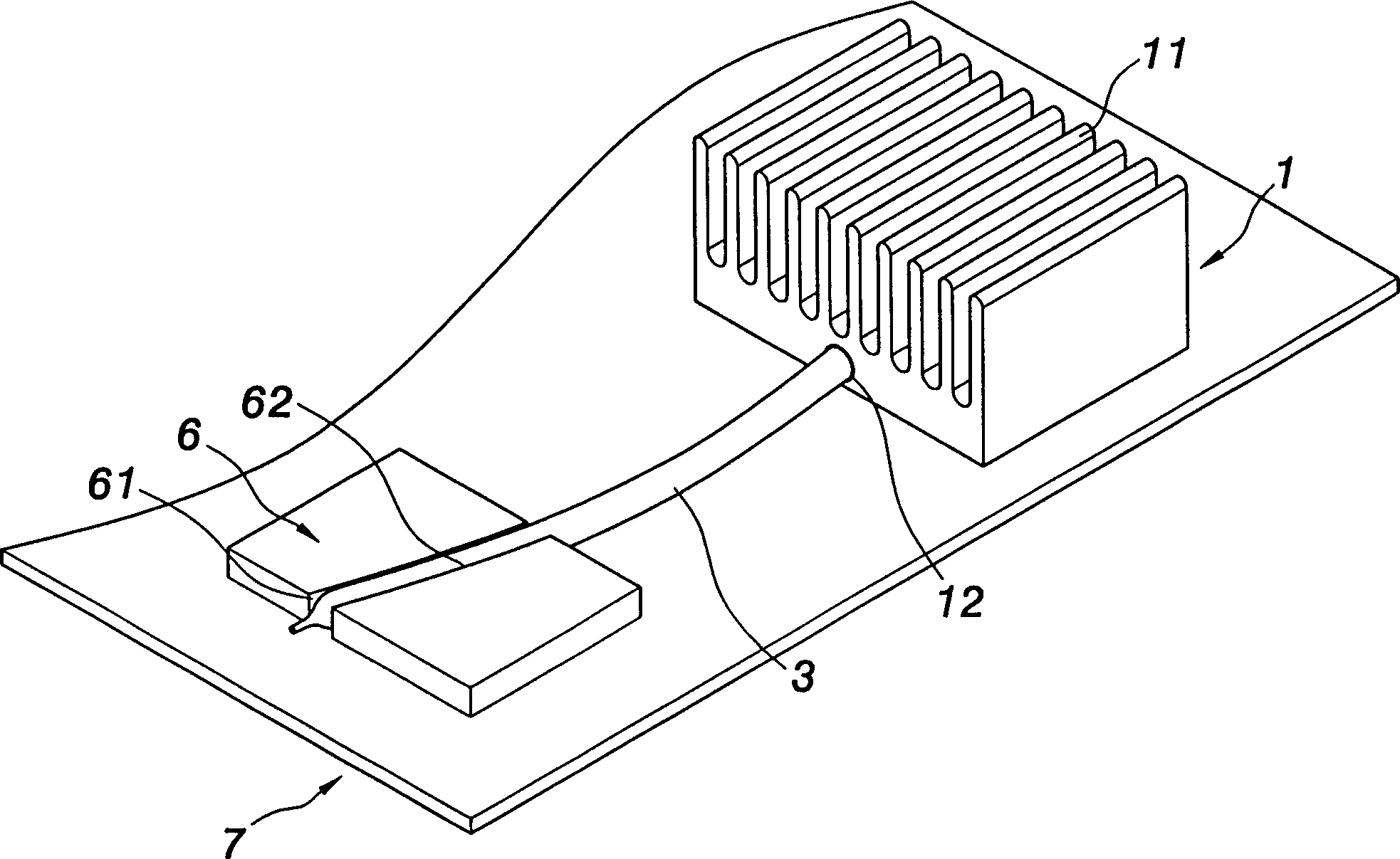
[0004] 1. It is obviously very troublesome to open the planting groove 12 on the cooling plate 1, and then insert the heat pipe 3;
[0005] 2. The heat pipe 3 and the cooling plate 1 are independent of each other, and there will be more or less gaps between the two, which will affect the heat conduction effect;
[0006] 3. The independent heat pipe 3 is easy to be damaged during manufacture, so there are a lot of unqualified products, resulting in waste;
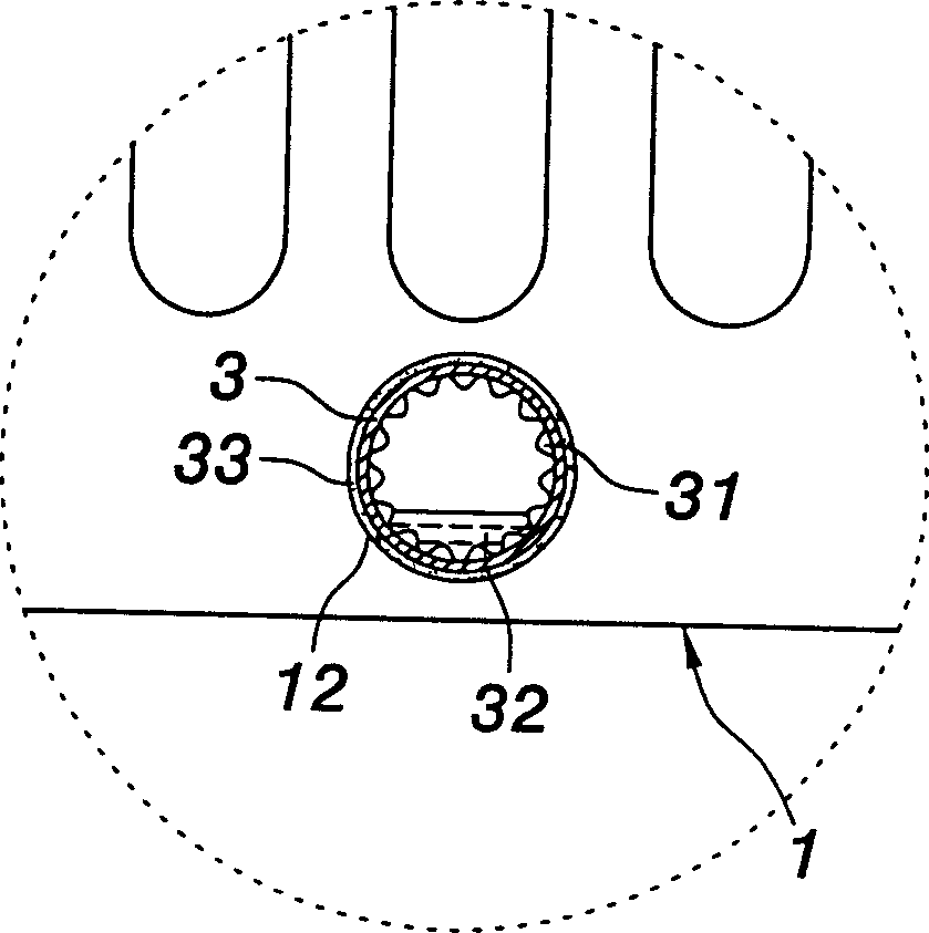
[0007] 4. Since the common heat pipe 3 must be bent as shown in the figure, it is easy to cause damage to the capillary structure 31 in the pipe;
[0009] 6. Since there are solder paste 33 and 62 between the heat pipe 3 and the plate body 6, and between the heat pipe 3 and the heat dissipation plate 1, it is easy to be affected by the thermal expansion and contraction caused by the long-term on and off of the machine, resulting in various The generation of the gap between the two not only affects the heat conduction, but also reduces the life span;
[0010] 7. Ordinary stand-alone heat pipes 3 are prone to rupture due to irresistible factors, and can no longer maintain a vacuum state. At the same time, it is also difficult to conduct heat energy to the heat dissipation plate 1, so that heat energy cannot be dissipated, resulting in heat dissipation of the body to be radiated. destruction;
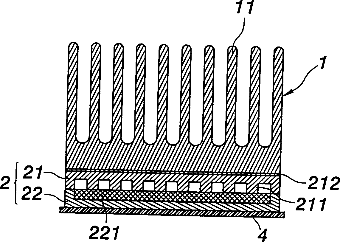
[0016] First, all of them will have the following major disadvantages in the case of accidental collision or fall: if it occurs in figure 1 In the structure shown, its heat pipe 3 will produce cracks and leak air, and then fail, so that the body to be radiated (not shown in the figure, such as the central processing unit, etc.) will be burned due to heat conduction interruption; if it occurs in figure 2 In the shown structure, the plate-shaped container 2 will produce cracks and leak air, and then fail, so that the heat energy from the heat dissipation body 4 (such as a central processing unit, etc.) can still be transferred to the heat dissipation plate 1 through the plate-shaped container 2 , but the plate-shaped container 2 will lose its expected effect, and the heat conduction efficiency will be delayed, and it will be slower than the most traditional heat dissipation method without the plate-shaped container 2
[0017] Second, the above-mentioned two common structures are too complicated and troublesome, and the cost is greatly increased, which is not in line with the principles of current commercial utilization.
like figure 1 As shown, after the heat sink 1 is inserted into the heat pipe 3 in one direction, another heat pipe cannot be inserted in the other vertical direction at all, so it cannot form a matrix arrangement
And as figure 2 As shown, although it is possible to form a matrix, except that each of the protrusions 211 must be troublesomely set up one by one to form a matrix arrangement, each of the protrusions 211 has a very high possibility again, which will be due to the aforementioned reasons. Therefore, even if it can form a matrix arrangement, it still has great defects.
[0019] fourth, figure 1 , figure 2 There must be solder paste 62, 33, 212 (or heat dissipation paste) in the common structure, and the solder paste or heat dissipation paste should not be too thick or too thin, which is quite troublesome to operate; it may even cause thermal expansion and contraction impact, resulting in regrets such as increased gap, cracks, reduced lifespan and high thermal resistance in the future

Method used


Image

  • Manufacture of heat pipe for heat dissipating plate
  • Manufacture of heat pipe for heat dissipating plate
  • Manufacture of heat pipe for heat dissipating plate

Examples


Embodiment Construction

[0049] see image 3 and cooperate Figure 4 , Figure 5 Shown, the present invention is a kind of manufacturing method of radiator plate heat pipe, and it mainly comprises following process:

[0050] The first process: first, a heat dissipation plate 5 should be manufactured to an appropriate size and shape for different heat dissipation designs.

[0051] The second process: applying a processing method to the heat dissipation plate 5 to produce the heat conduction channel 51; and it is necessary that the other end of the heat conduction channel 51 is not penetrated. The processing methods can be drilling, electric discharge, water jet, etc., and it does not penetrate to the other end of the cooling plate 5 .

[0052] The third process: sealing the opening ends of each heat conduction channel 51 , and at least one opening end must be reserved. It seals each opening end, and in order to avoid deformation caused by peripheral welding and ensure the airtightness of the heat con...


PUM


Abstract

The manufacture of heat pipe for heat dissipating plate includes machining the heat dissipating plate to form several heat conducting passages with enclosed end; enclosing the opened ends of the heatconducting passages while leaving at least one; filling working fluid and pumping vacuum via the left end and finally sealing.

Description

technical field [0001] The present invention relates to a method for manufacturing heat pipes of a heat dissipation plate, in particular to a method of directly forming a heat pipe in a heat dissipation plate; it has excellent heat conduction efficiency, excellent structural strength, and can Maintain extremely flat contact, and the structure tends to be simplified, the process is shortened, the cost is reduced, the pass rate is improved... and many other effects. Background technique [0002] Generally, heat pipes are used to quickly conduct heat energy to heat sinks for heat dissipation, please refer to figure 1 As shown, it is fixed on an aluminum plate body 7 with a heat dissipation plate 1 and a plate body 6; the heat dissipation plate soil with many ribs 11 is provided with a planting groove 12, and the plate body 6 obliquely breaks out a groove 61 . the heat pipe 3, see Figure 1A As shown, in addition to the capillary structure 31 on the inner wall, a working flui...

Claims


Application Information

Patent Timeline
Patent Type & Authority Applications(China)
IPC IPC(8): H01L23/427
Inventor 余英祺詹鸿斌王威德
Owner HONG MANG
Learn More