Electric/mechanic operating mechanism of hydraulic turbine blades

An operating mechanism and water turbine technology, applied in the direction of machines/engines, electromechanical devices, hydroelectric power generation, etc., can solve the problems of oil pump wear, complex structure, difficult sealing, etc., achieve reduced wheel-hub ratio, significant economic benefits, increase flow and The effect of effort

An operating mechanism and water turbine technology, applied in the direction of machines/engines, electromechanical devices, hydroelectric power generation, etc., can solve the problems of oil pump wear, complex structure, difficult sealing, etc., achieve reduced wheel-hub ratio, significant economic benefits, increase flow and The effect of effort

CN1424500AInactive Publication Date: 2003-06-18周泰经

Image

  • Electric/mechanic operating mechanism of hydraulic turbine blades
  • Electric/mechanic operating mechanism of hydraulic turbine blades

Examples


Embodiment Construction

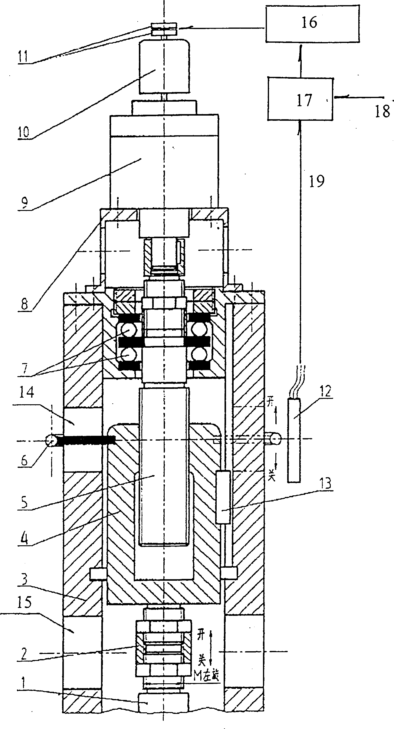
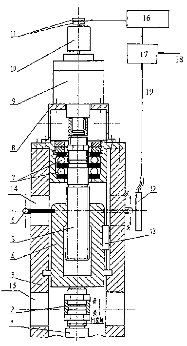
[0017] as attached figure 1 Summary of the invention: the present invention adopts a kind of electric / mechanical operating mechanism to replace the oil cylinder system to adjust the opening (rotation angle) of the water turbine blade. The devices are all installed on the unit main shaft 3 and rotate together with the main shaft. Its servo system adopts DC servo motor 10 and harmonic deceleration device 9 and its driving power supply 16 and control circuit 17, and the servo motor control circuit 17 and power supply 16 are then connected with the servo motor through slip ring 11. The transmission mechanism adopts the screw nut sleeve structure, which is placed in the main shaft of the unit. The output shaft of the DC servo motor and the harmonic reduction device drives the trapezoidal screw 5 forward and reverse. Connect the operating shaft 1, and the operating shaft is directly connected to the paddle operating mechanism in the runner body of the water turbine.

[0018] The D...


PUM


Abstract

An electromechanical operation mechanism of propeller for water turbine can be used to adjust the aperture of propeller for water turbine in stead of hydro-cylinder system. The output shaft of servomotor and reduction gear will be connected with the trapezoidal screw in main shaft of machine set as the up section of trapezoidal nut sheath to be connected to the screw thread of trapezoidal screw and the down end to operation shaft which directly connects with the operation mechanism of propeller in rotary wheel body of water turbine. The servomotor and reduction gear will be fixed at up end of main shaft for machine set through supporting frame and be connected to the main shaft by bilateral thrust bearing. It is better to use DC servomotor and harmonic reduction gear and there will a feedback device near trapezoidal nut sheath to reflect the rotary angle changes of propeller.

Description

technical field [0001] The invention relates to an electric / mechanical operating mechanism for blades of water turbines, which is used for adjusting the opening of paddle blades of water turbines. Background technique [0002] The paddle adjustment of the paddle turbine usually leads the pressure oil from the governor operating oil pipe to the oil receiver at the upper end of the vertical paddle turbine generator set, and enters along the hollow main shaft of the unit through the inner and outer oil pipes. The blade servomotor (operating cylinder) in the runner body of the lower turbine, and then the operating cylinder drives the operating mechanism in the runner body to make all blades forward and reverse at the same time to adjust the flow. [0003] The root pivot of the blade and its bushing are prone to wear when the blade is subjected to huge water pressure for a long time and rotates continuously. After wear and deformation, other sealing materials cannot prevent a lar...

Claims


Application Information

Patent Timeline
18 Jun 2003
Publication
CN1424500A
IPC
F03B3/06; G05D3/12; H02K7/06
CPC
Y02E10/223; Y02E10/20
Inventors
周泰经; 魏守平