Fluid mixing method and device thereof

A fluid mixing and fluid technology, applied in mixers, chemical instruments and methods, shaking/oscillating/vibrating mixers, etc., can solve problems such as insufficient working range, achieve short mixing time, low energy consumption, and accelerated chemical reactions Effect

Inactive Publication Date: 2003-11-19
贡有成
View PDF1 Cites 14 Cited by
  • Summary
  • Abstract
  • Description
  • Claims
  • Application Information

AI Technical Summary

Problems solved by technology

[0004] In order to overcome the deficiency that the working range of the existing rotary agitator is not la

Method used


Image

  • Fluid mixing method and device thereof
  • Fluid mixing method and device thereof

Examples


Embodiment Construction

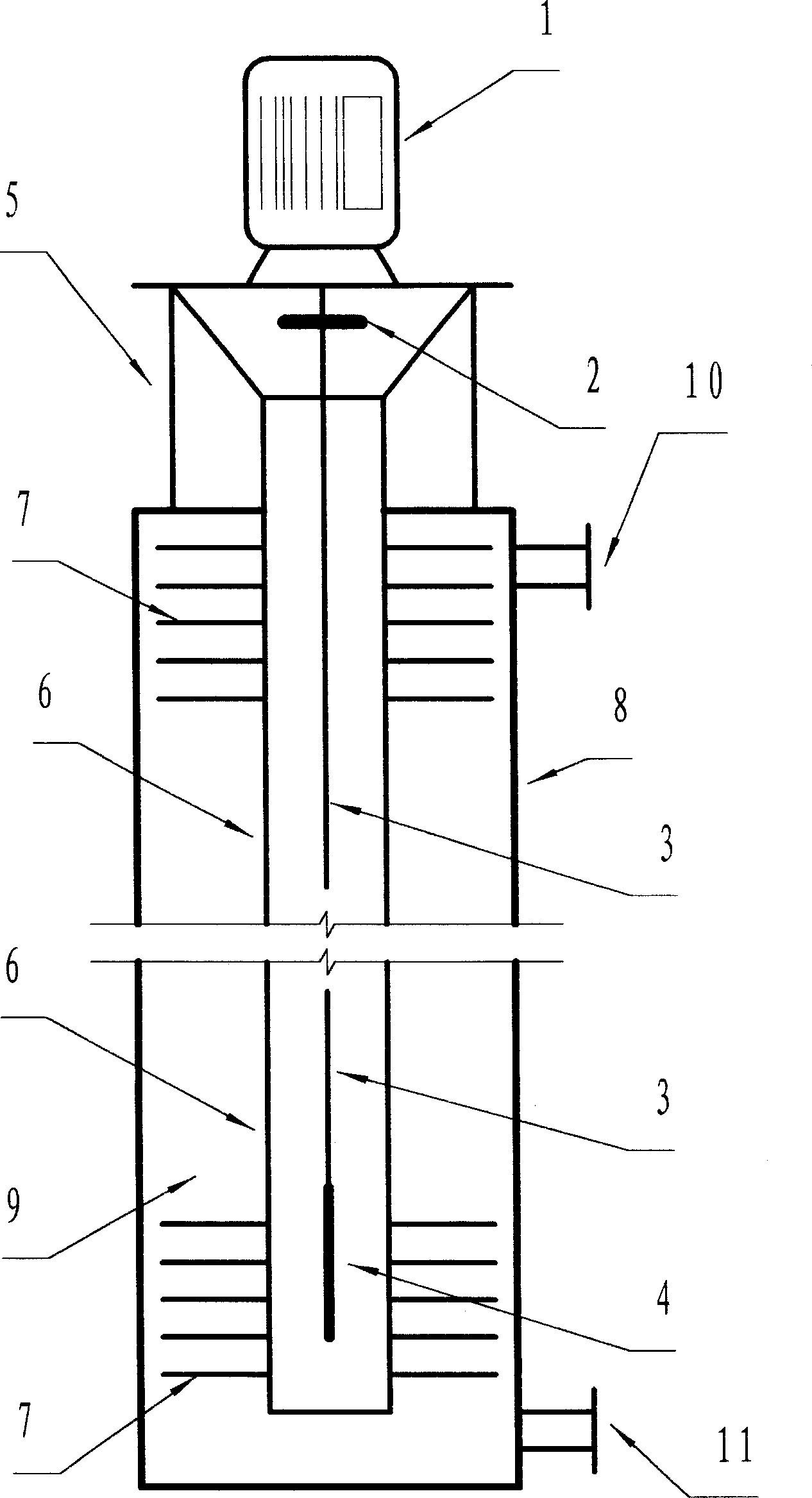
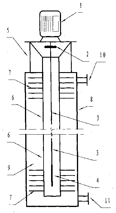
[0035] The essence of the fluid mixing method of the present invention is to transform high-speed rotational stirring into rigid body high-frequency oscillation. The preferred method is to install a number of elastic vibrating fins on the outer wall of the rigid body, so as to transmit the high-frequency vibration to all the layers around the rigid body, where there is fluid, the vibrating fins are installed. Another preferred method is to make the fluid mixing device move in the fluid container, as long as an opening coincident with the moving track of the rigid body is provided on the upper cover of the container, manual or mechanical movement can be realized. This method eliminates the need to install oscillating fins and move the device to where the fluid needs enhanced mixing.

[0036] Such as figure 1 As shown, a fluid mixing device implementing the above method is composed of a vibrator and an oscillator, wherein the vibrator is composed of a prime mover (1) and a perc...


PUM


Abstract

A fluid mixing method includes such steps as driving beater to rotate at high-speed, beating the rigid body of oscillator to generate high-frequency oscillation, and transferring the energy to two or more kinds of fluid around the rigid body to mix them together. Its equipment is composed of a beater consisting of flexible axle, axle coupling and beating head, and a rigid body of oscillator, which surrounds the high-speed beating head. Its advantages are short time and low energy consumption.

Description

Technical field [0001] The invention relates to a fluid mixing method and a device thereof, in particular to a fluid mixing method and a device thereof in industries such as chemical industry, medicine, paint, cosmetics and environmental protection. Background technique [0002] Relying on the stirrer to rotate in the stirring tank to stir the liquid is the most common mixing method for dispersing liquid, gas or solid particles into the liquid in chemical production. Although there are many types of agitators, such as propeller type, turbine type, anchor type, etc., their common feature is rotating stirring. The power head of the rotating agitator works in a limited area (range) to achieve uniformity. The time is long, or the mixing speed is slow, the production efficiency is low, and the power consumption is large. [0003] In order to overcome the deficiencies of the agitator, Chinese patent 012112216 discloses a "vibration mixing emulsification machine", which includes a...

Claims


Application Information

Patent Timeline
IPC IPC(8): B01F11/00
Inventor 贡有成
Owner 贡有成
Why Eureka
Try Eureka