Plasma processing device
A plasma and processing device technology, which is applied in the field of plasma processing devices, can solve the problems of difficult formation of microwave plasma and increased dielectric loss, and achieve the effect of small thermal conductivity and elimination of electric field concentration
- Summary
- Abstract
- Description
- Claims
- Application Information
AI Technical Summary
Problems solved by technology
Method used
Image

Examples
Embodiment 1
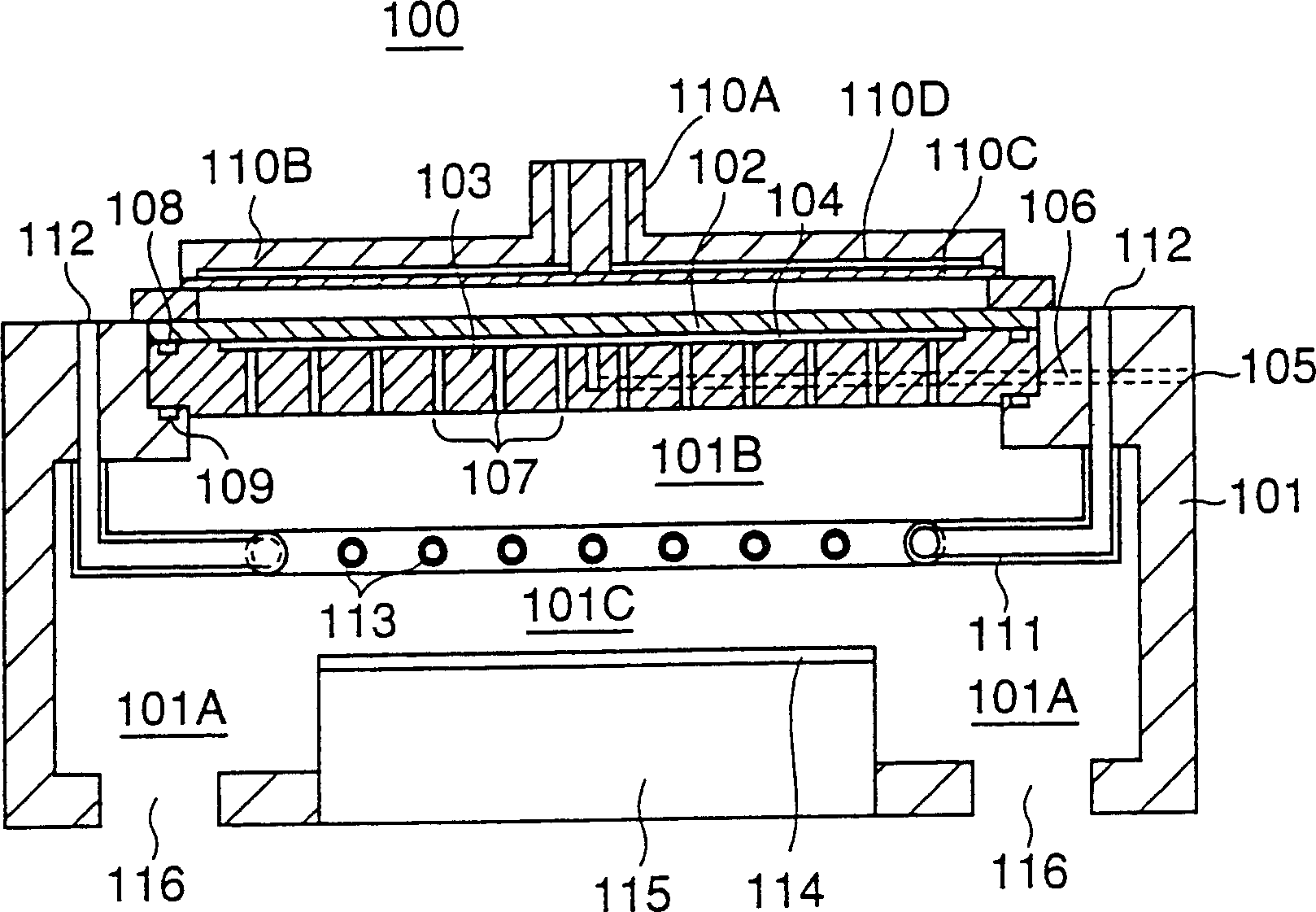
[0049] Figure 3A , Figure 3B The configuration of the microwave plasma processing apparatus 10 according to the first embodiment of the present invention is shown.
[0050] refer to Figure 3A , the above-mentioned microwave plasma processing apparatus 10 comprises: a processing container 11; being arranged in the above-mentioned processing container 11, holding the substrate 12 to be processed by an electrostatic chuck, preferably formed by heat isotropic pressing (HIP) 2 o 3 Or the holding table 13 made of AlN. In the above-mentioned processing container 11, in the space 11A surrounding the above-mentioned holding table 13, there are at least two locations, preferably three or more locations, at regular intervals, that is, in an approximately axisymmetric relationship with respect to the substrate 12 to be processed on the above-mentioned holding table 13. An exhaust port 11a is formed. The above-mentioned processing container 11 is exhausted and depressurized by pump...
Embodiment 2
[0083] Figure 7 The configuration of a plasma processing apparatus 10A according to Embodiment 2 of the present invention is shown. exist Figure 7 In , the same reference numerals are attached to the previously described parts, and description thereof will be omitted.
[0084] refer to Figure 7 , the plasma processing apparatus 10A has a Figure 3A , Figure 3B The structure of the plasma processing apparatus 10 is the same, but the shower plate 14 is removed, and the gas introduction port 11P extending from the gas introduction port 11p extends into the space 11B in the processing container 11 .
[0085]In such a configuration, by exciting the plasma gas introduced from the gas introduction port 11p with microwaves supplied from the radiation slot antenna 20, high-density plasma can be formed in the space 11B.
[0086] The high-density plasma formed in this way is less uniform than the high-density plasma obtained by using the shower plate 14 , but the structure of th...
Embodiment 3
[0090] Figure 8 The configuration of a microwave plasma processing apparatus 10B according to Example 3 of the present invention is shown. exist Figure 8 In , the same reference numerals are attached to the previously described parts, and description thereof will be omitted.
[0091] refer to Figure 8 The microwave plasma processing apparatus 10B of the present embodiment has a structure similar to the microwave plasma processing apparatus 10 of the previous embodiment, but in the microwave plasma processing apparatus 10B of the present embodiment, the above-mentioned processing gas supply mechanism 31 is removed. In addition, the protruding portion 11b of the processing container 11 is also formed in a circular shape on the lower surface, thereby avoiding abnormal discharge.
[0092] In the plasma processing apparatus 10B having such a structure, microwaves are reflected by the plasma formed directly under the shower plate 14, and as a result, microwaves do not reach th...
PUM
 Abstract
Description
Claims
Application Information
 - R&D
- Intellectual Property
- Life Sciences
- Materials
- Tech Scout
- Unparalleled Data Quality
- Higher Quality Content
- 60% Fewer Hallucinations
Browse by: Latest US Patents, China's latest patents, Technical Efficacy Thesaurus, Application Domain, Technology Topic, Popular Technical Reports.
© 2025 PatSnap. All rights reserved.Legal|Privacy policy|Modern Slavery Act Transparency Statement|Sitemap|About US| Contact US: help@patsnap.com