High efficiency switching amplifiers

A switching amplifier and switching technology, used in amplifiers, low-frequency amplifiers, improving amplifiers to improve efficiency, etc., can solve problems such as no bidirectional energy transmission capability, slowing down signal leakage inductance, and difficulty in compensating for transformer delays.

Inactive Publication Date: 2003-12-17
ENFISEX
View PDF5 Cites 7 Cited by
  • Summary
  • Abstract
  • Description
  • Claims
  • Application Information

AI Technical Summary

Problems solved by technology

This amplifier is not capable of driving typical highly inductive loudspeakers that require two-way energy transfer to and from a DC supply
U.S. Patent No. 5,986,498 provides the same rectification of the carrier voltage, so in addition to the limited bandwidth and high distortion due to its phase lag network, and the difficulty of compensating for delays in the transformer and leakage inductance that would slow down the signal passing , also has no two-way energy transfer capability

Method used


Image

  • High efficiency switching amplifiers
  • High efficiency switching amplifiers
  • High efficiency switching amplifiers

Examples


Embodiment Construction

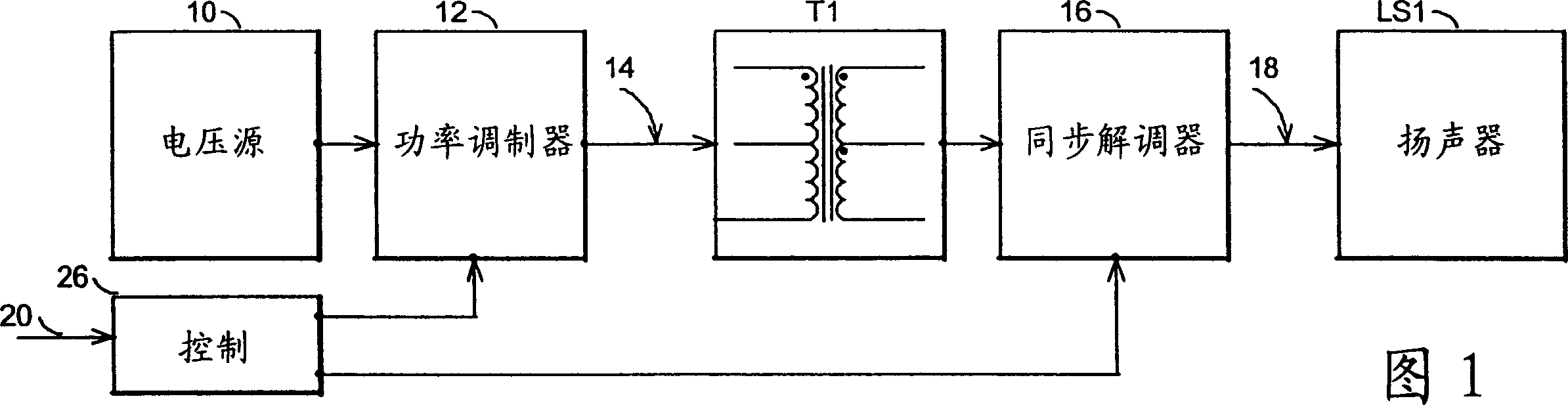
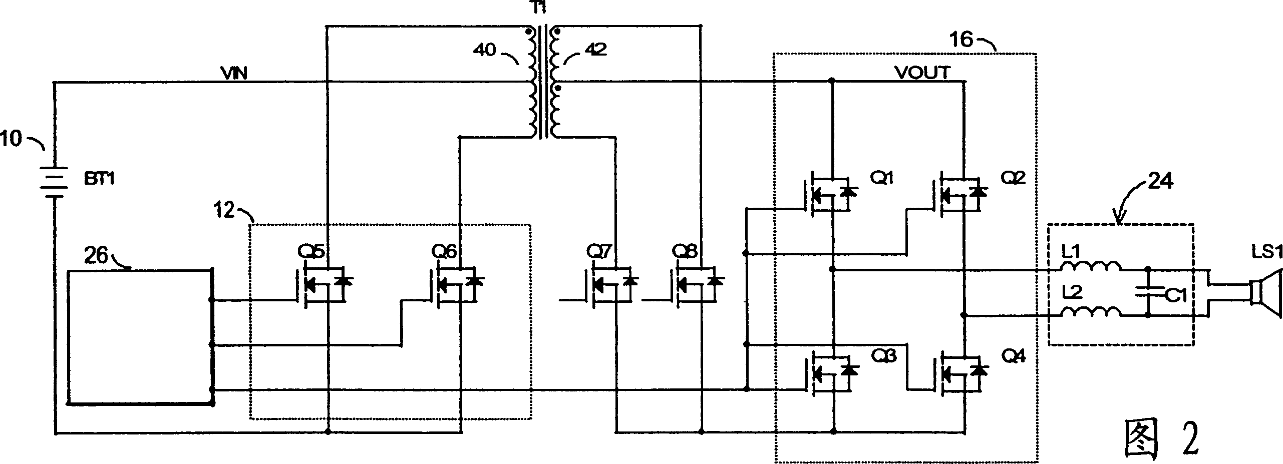
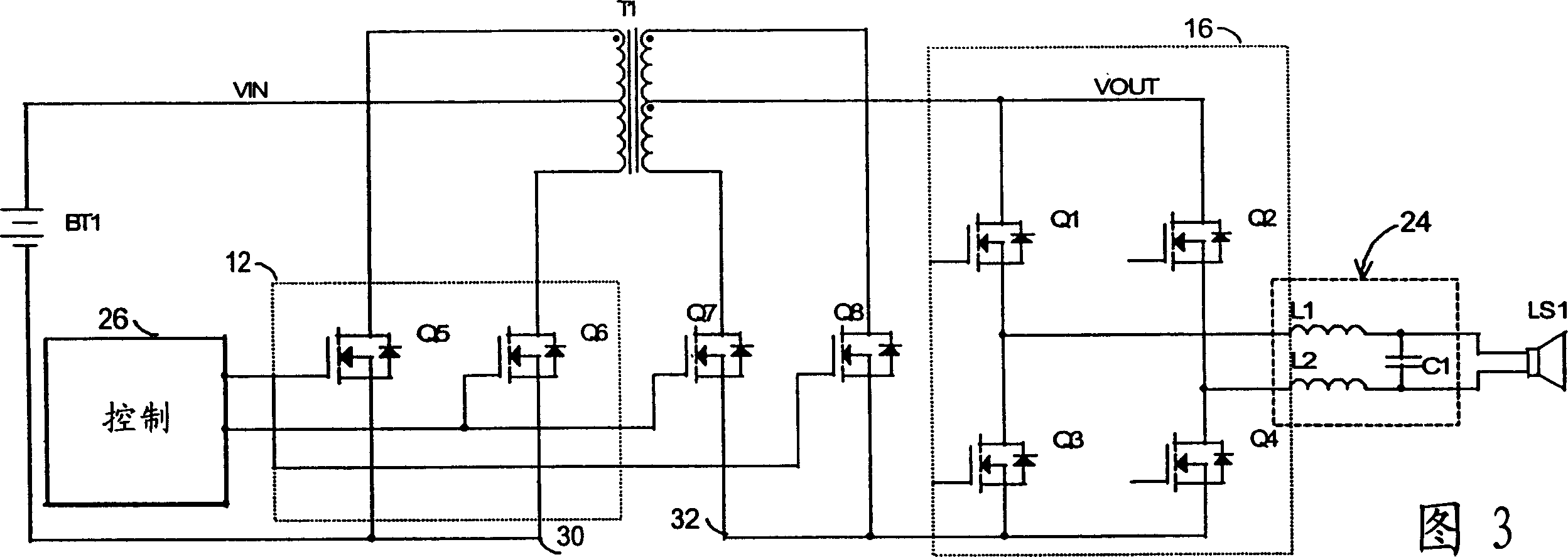
[0026] In the general block diagram of FIG. 1, the class N switching amplifier series of the present invention includes a voltage source 10 supplying power to a power modulator 12 which generates a PWM (pulse width modulated) voltage 14 to drive a transformer T1. Synchronous demodulator 16 reconstructs the signal from PWM voltage 14 conducted by transformer T1 into an amplified audio signal 18 to drive speaker LS1. A controller 26 receiving an audio signal 20 as input controls the operation of the power modulator 12 and synchronous demodulator 16 by driving them with corresponding pulses. The power modulator 12 and its matched synchronous demodulator 16 process the PWM voltage 14 substantially simultaneously.

[0027] To clarify definitions and terminology, a modulator is typically an electronic circuit or device capable of providing a pulse or waveform of which at least one of its characteristics such as amplitude, frequency, phase, pulse duty cycle, energy, etc. Variety. T...


PUM


Abstract

A family of switching amplifiers with reduced component count. The amplifiers have a power modulator (12) comprising ground-referenced switches driving a tapped transformer (T1). A synchronous demodulator (16) transforms modulated voltages back to audio signal. In one embodiment, the synchronous demodulator (16) comprises switches in a H-bridge configuration selectively connecting the transformer (T1) to ground reference through a loudspeaker, driving it with bipolar voltages. Different embodiments using MOSFETs to implement the functions of a synchronous demodulator (16) using bi-directional switches reduce total component count and increase the efficiency of the amplifiers. Timing control of the power modulator (12) and the synchronous demodulator (16) enables zero current switching of the power modulator (12).

Description

technical field [0001] This invention relates to power conversion, and more particularly to switching power amplifiers. Background technique [0002] Class D switching amplifiers, or digital amplifiers, are very familiar amplifiers to electronics engineers. In automotive applications, where the vehicle chassis forms a ground reference, the amplifier must operate from the battery voltage, which can be as low as 7V when the ambient air temperature is sub-zero, and even as low as 3.5V when the starter is engaged. As a result of the lowest battery voltage, high-power switching amplifiers operating from battery voltage typically require a boost converter as shown in Figure 1A, consisting of a boost inductor, main switch, boost rectifier, and storage capacitor to handle large current values. The amount of current that a high power amplifier must handle can be very large, in the tens of amps for an output power of about 50-100 watts. The traditional approach of using a boost conv...

Claims


Application Information

Patent Timeline
Patent Type & Authority Applications(China)
IPC IPC(8): H02M3/335H03F1/02H03F3/185H03F3/217H03F3/393
CPCH02M3/33576H03F3/393H03F3/2173
Inventor 特拉·托·源
Owner ENFISEX
Why Eureka
Try Eureka