Method and device for sending and receive frquency sweep laser beacon

A laser beacon and beacon receiving technology, applied in the field of laser beacons, can solve the problems that the transmission dead point affects the overall capture performance, reduces the search and capture time of both communication parties, and changes in transmittance, etc.

Inactive Publication Date: 2003-12-24
WUHAN INST OF PHYSICS & MATHEMATICS CHINESE ACADEMY OF SCI
View PDF0 Cites 2 Cited by
  • Summary
  • Abstract
  • Description
  • Claims
  • Application Information

AI Technical Summary

Problems solved by technology

The atomic beacon invented by the United States in the mid-to-late 1990s is used in the STRV-2 satellite. The atomic beacon is composed of a beacon emitting laser and a beacon receiver. Because the optical filter in the beacon receiver adopts the Faraday effect The receiving bandwidth of the device is 2 orders of magnitude narrower than that of ordinary optical filters, so it realizes the large field of view reception under the condition of low-power transmitting beacons, which not only greatly reduces the search and capture time of both communication parties, but also improves the search and acquisition time. capture success rate, but because of the narrow receiving bandwidth, the laser Doppler frequency shift between the two high-speed moving satellites makes the frequency of the beacon laser fall outside the transmission band of the atomic filter, thus To make the beacon receiver unable to receive the beacon laser signal, the technology currently used is: dual-frequency emission of the laser and multi-peak transmission reception of the atomic filter. Although this method is technically simple, it uses two emitting lasers The frequency compensates for the four transmission peaks of the receiving atomic filter, so there is a disadvantage that the transmission rate changes under different Doppler frequency shifts, and there may be transmission dead spots at individual Doppler frequency shift points that affect the overall capture performance
In addition, the maximum frequency shift compensation of this Doppler frequency shift compensation technology is generally only about ±10 GHz, but the frequency shift of low-orbit-low-orbit satellite laser communication often exceeds ±10 GHz. Therefore, the Doppler frequency of the existing beacon system Frequency shift compensation technology cannot meet the requirements of Doppler frequency shift compensation for many satellite laser communications

Method used


Image

  • Method and device for sending and receive frquency sweep laser beacon
  • Method and device for sending and receive frquency sweep laser beacon
  • Method and device for sending and receive frquency sweep laser beacon

Examples


Embodiment Construction

[0015] The present invention will be further described below in conjunction with the accompanying drawings.

[0016] The frequency-sweeping laser beacon transceiver method consists of two parts: laser beacon emission and beacon reception. The beacon reception adopts Faraday effect device filtering, and the laser beacon emission adopts the method of frequency scanning to emit laser light.

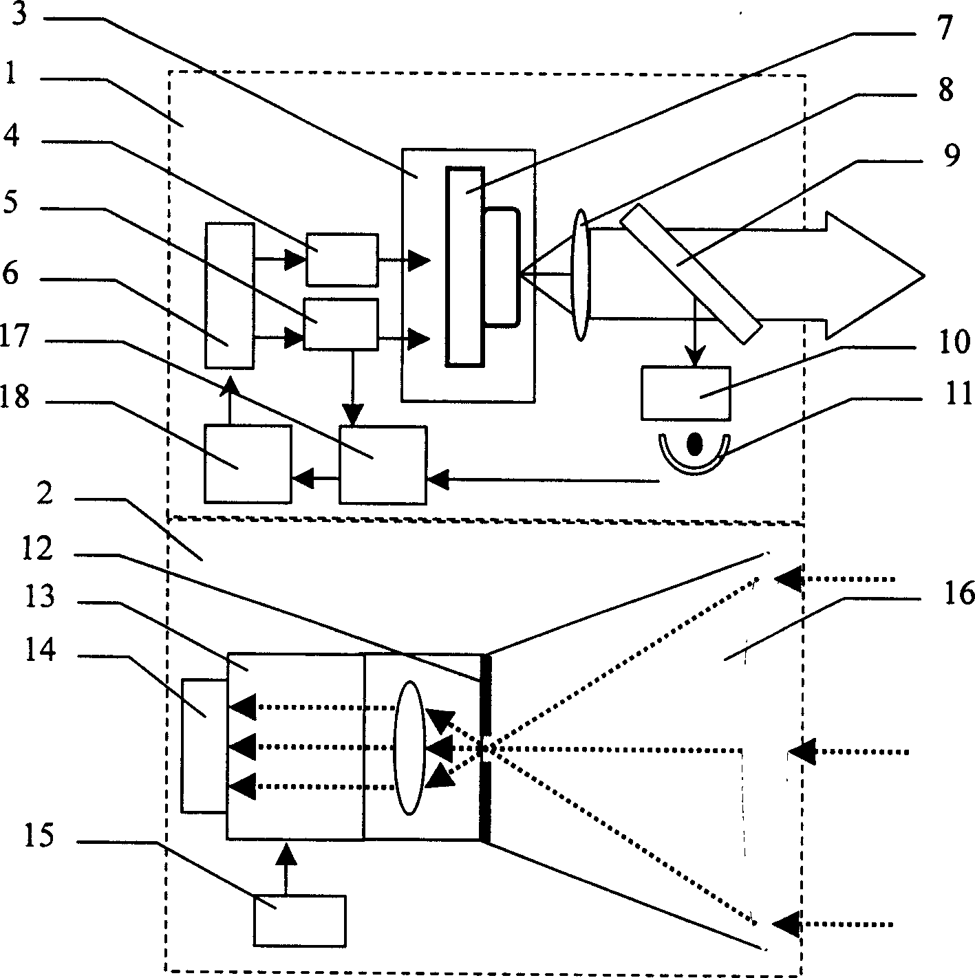
[0017] Depend on figure 1 As we know, the present invention consists of a laser beacon transmitter and a beacon receiver 2. The laser beacon transmitter adopts a frequency-sweeping semiconductor laser beacon transmitter 1, and the beacon receiver 2 adopts a Faraday effect device 13 to filter light. The frequency-sweeping semiconductor laser beacon transmitter 1 outputs a frequency-scanning laser, and its frequency center is based on the atomic transition line,

[0018] Sweep frequency semiconductor laser beacon transmitter 1 consists of constant temperature controller 3, DC driver 4, freque...


PUM


Abstract

The invented method consists of two parts: laser beacon transmission and the beacon receiving. The corresponding device includes the laser beacon emitter and the beacon receiver. The beacon receiver is a Faraday effect device for filtering. The laser beacon emitter uses the frequency sweep type semiconductor laser beacon emitter. The invention has the advantages of low power consumption, high output efficiency, easy to realize large power, more narrow bandwidth, visual field extended to 3 times, as well as simple structure, high automation degree and reliable operation etc.

Description

Technical field: [0001] The present invention relates to laser beacons, and more particularly to laser beacon transceivers. Background technique: [0002] Laser beacons are an important part and prerequisite of the space laser communication system, and they are a bridge for communication between the two parties, especially in satellite laser communication. Since the divergence of the communication laser beam is very small, the beacon is the satellite to find important symbol of the opponent. The atomic beacon invented by the United States in the mid-to-late 1990s is used in the STRV-2 satellite. The atomic beacon is composed of a beacon emitting laser and a beacon receiver. Because the optical filter in the beacon receiver adopts the Faraday effect The receiving bandwidth of the device is 2 orders of magnitude narrower than that of ordinary optical filters, so it realizes the large field of view reception under the condition of low-power transmitting beacons, which not only...

Claims


Application Information

Patent Timeline
Patent Type & Authority Applications(China)
IPC IPC(8): H04B10/25H04B10/40
Inventor 李发泉程学武高克林龚顺生
Owner WUHAN INST OF PHYSICS & MATHEMATICS CHINESE ACADEMY OF SCI
Why Eureka
Try Eureka