
Anode for lithium secondary battery and lithium secondary battery

A lithium battery and positive electrode technology, which is applied in the positive electrode field of the battery, can solve the problems of non-corrosion resistance and undurable current collectors, etc.

Inactive Publication Date: 2003-12-24
SUBARU CORP +1
View PDF0 Cites 18 Cited by
  • Summary
  • Abstract
  • Description
  • Claims
  • Application Information

AI Technical Summary

Problems solved by technology

Through these treatments, although a larger current can be passed through the current collector, there is a problem that it is not resistant to corrosion due to long-term use
Also, in a positive electrode containing an organic sulfur compound as an active material, if a current collector composed of aluminum is used, this loss of activity becomes significant and the current collector is not durable.

Method used


Image

  • Anode for lithium secondary battery and lithium secondary battery
  • Anode for lithium secondary battery and lithium secondary battery
  • Anode for lithium secondary battery and lithium secondary battery

Examples


Embodiment 1

[0102] [Production of current collector]

[0103] 20% by weight of graphite with an average particle diameter of 5 μm, 20% by weight of carbon black, 20% by weight of polyamideimide resin (trade name: N8020 manufactured by Toyobo Co., Ltd.), 40% by weight of solvent N-methyl - 2-Pyrrolidone (NMP) is fully mixed to prepare a slurry. This slurry is applied on the surface of a conductive substrate made of aluminum (Al) foil manufactured by Nilaco Co., Ltd. with a bar to form a predetermined film thickness, then preheated at 150°C for 1 hour, and then heated at 200°C It was cured for 1 hour to form a current collector. At this time, the above-mentioned aluminum foil is not subjected to special surface treatment, but is used as it is.

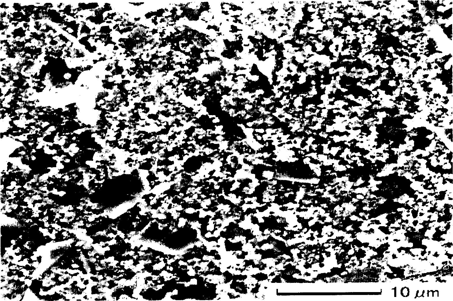
[0104] In the obtained current collector, a carbon-based material film having a thickness of 10 to 30 μm was formed on the surface of a conductive substrate formed of aluminum foil. figure 1 is a photograph of the surface of the current collector...

Embodiment 2

[0116] [Production of current collector]

[0117] A carbon-based conductive paint ink (manufactured by Acheson Corporation, trade name: EB-815) was used as the slurry. The ink contains: 5-20% by weight of artificial graphite; 5-20% by weight of carbon black; 5-20% by weight of polyamide imide resin; 0-1% by weight of butyral resin; N-methylpyrrolidone solvent . Apply this carbon-based conductive paint ink on the entire surface of a conductive substrate formed of 40 μm thick Al foil (H8079 material) with a direct gravure coating device, preheat at 150°C for 1 hour, and then heat at 250°C Under heating for 30 minutes to solidify to form a current collector.

[0118] In the obtained current collector, a carbon-based material film having a thickness of 5 to 20 μm was formed on the surface of a conductive substrate made of aluminum foil. This carbon-based material film has carbon-based material particles with an average particle size of 10 μm, and the weight ratio of carbon-base...

Embodiment 3

[0130] A current collector was produced by forming a carbon-based material on the surface of the substrate in the same manner as in Example 2, except that a titanium (Ti) foil having a thickness of 15 μm was used as the conductive substrate. Using this current collector, a three-electrode electrolyte battery was produced in the same manner as in Example 2, and electrochemical measurements were performed. As a result, the same characteristics as in Example 2 using Al foil as the conductive substrate were obtained.


PUM

PropertyMeasurementUnit
The average particle sizeaaaaaaaaaa
Thicknessaaaaaaaaaa
Thicknessaaaaaaaaaa

Abstract

A positive electrode for lithium secondary battery includes a collector obtained by forming a carbonaceous material film on the surface of a conductive substrate, and a positive electrode material layer carried on the carbonaceous material film side of the collector and containing an organic sulfide compound as a main active material.

Description

technical field [0001] The present invention relates to a positive electrode for a lithium storage battery and a lithium storage battery, and particularly to a lithium storage battery suitable for use as a power source for portable electronic devices and electric vehicles requiring high energy density, and a positive electrode for the battery. Background technique [0002] Existing lithium batteries, the positive electrode uses lithium cobalt oxide (LiCoO 2 ), lithium manganate (LiMn 2 o 4 ) and other inorganic metal oxides, carbon-based materials are used for the negative electrode. It is known that the theoretical capacity of these electrode materials is: the positive electrode material is 100-150 Ah / kg, correspondingly, the negative electrode material is 370-800 Ah / kg, which has a theoretical capacity more than three times that of the former. [0003] Therefore, in order to form a high-performance lithium battery, the development of new cathode materials capable of ach...

Claims


Application Information

Patent Timeline
IPC IPC(8): H01M4/06H01M4/13H01M4/137H01M4/36H01M4/38H01M4/58H01M4/60H01M4/62H01M4/66H01M10/05H01M10/0525
CPCY02T10/7011H01M4/608H01M4/666H01M10/052H01M4/667H01M4/5825H01M4/661H01M2004/028H01M4/624H01M4/60H01M4/663H01M4/38Y02E60/12H01M4/668H01M2300/0085Y02E60/122Y02E60/10H01M4/58H01M4/13H01M10/0525
Inventor 山口秀一郎浜崎显一增田壮一郎下村猛小山升
Owner SUBARU CORP
Learn More