Information record mdeium, information recored method and information replay method

A technology for information recording and media, applied in recording/reproducing/deleting methods, optical recording/reproducing/erasing methods, temperature recording methods, etc., can solve the problem of swinging, very large, and uncontrollable balls at the beginning and end of recording marks size distribution etc.

Inactive Publication Date: 2004-02-11
HITACHI LTD
View PDF2 Cites 5 Cited by
  • Summary
  • Abstract
  • Description
  • Claims
  • Application Information

AI Technical Summary

Problems solved by technology

[0006] In order to perform ultra-high-density recording on optical disks, photoelectric disks, and thermal disks, there are binary recording or multi-valued recording methods in which the length of the recording mark is finely adjusted. Although this method can increase the density in principle, it cannot In fact, due to various reasons, the start and end of the recording mark are wobbled, and it is difficult to increase the density.
In addition, in order to actually increase the recording density, multi-layering is ideal, but since recording is performed by changing the position of the focal point in a method such as a 2-layer DVD, spherical aberration is likely to occur on a recording medium with more than 3 layers. It is a problem to have a bad influence on the light absorption of the layer on the light incident side
In addition, in multilayer (3-dimensional) recording using 2-photon absorption of a material transparent to recording light, there is a problem that a very large or short-pulse laser is required because the transition probability of 2-photon absorption is low.
In addition, in wavelength multiplex recording using latex balls, there is a problem that the intensity of the reproduced signal varies greatly depending on the wavelength due to the inability to control the distribution of ball sizes.

Method used


Image

  • Information record mdeium, information recored method and information replay method
  • Information record mdeium, information recored method and information replay method
  • Information record mdeium, information recored method and information replay method

Examples


Embodiment 1

[0026] (structure, manufacturing method)

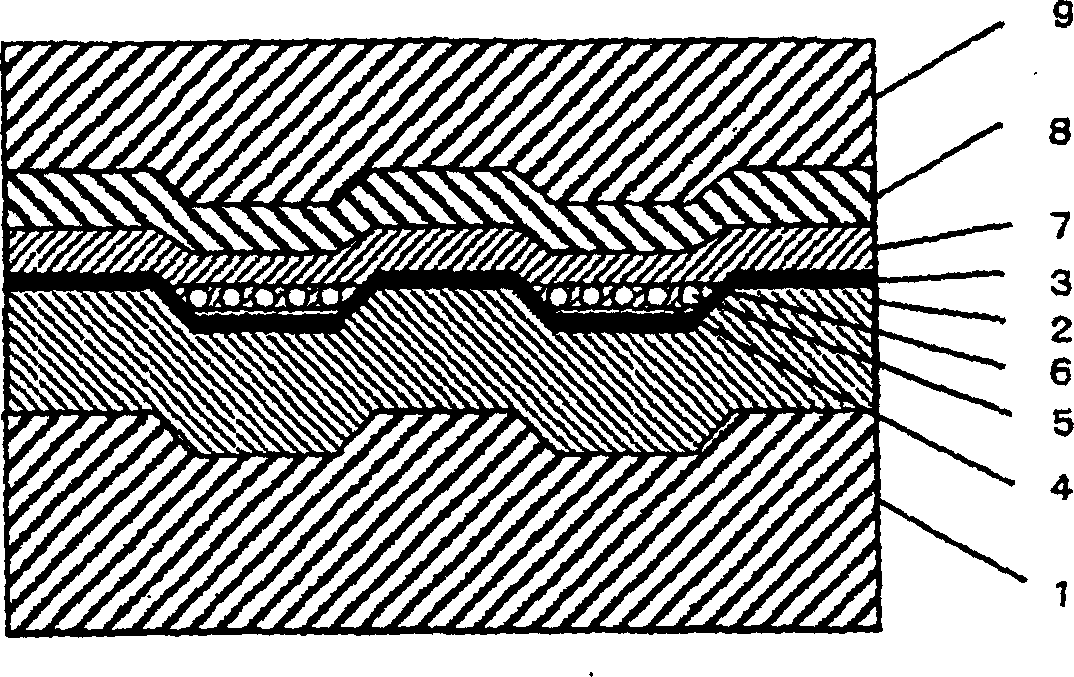
[0027] The recording medium of the present invention has figure 1 structure shown.

[0028] This medium was produced as described below. First, on a surface with a diameter of 8 cm and a thickness of 0.6 mm, there is a tracking groove (width 0.15 microns) for recording in a groove with a track pitch of 0.4 microns and a depth of 25 nm (here, land recording viewed from the light spot). , on the polycarbonate substrate 1 that expresses the address through the swing of the groove, the film thickness of 50nm is formed by (ZnS) 80 (Sio 2 ) 20 The lower protective layer 2 is formed. A phase-change recording film 3 made of Ge2Sb2Te5 having a film thickness of 10 nm was formed thereon. The groove pattern is transferred to the surface of the substrate by using a nickel master plate coated with a photoresist film on the original plate. As described in J.Am.Chem.Soc.vol.124, No.12, p2884 (2002) of the paper J.Am.Chem.Soc.vol.124, No.12, p...

Embodiment 2

[0071] The recording medium and device structure are the same as in Embodiment 1, but multi-valued recording is used as the recording method. Multi-valued recording is performed by changing the ratio of recording marks to the unit length on the recording track. In the case of performing multi-valued recording on a common phase-change recording medium, as in Figure 8 on page 20 (2001) of the Proceedings of the paper PCDOS2001 by M.Horie et al. Figure 4 As shown, distortion in the shape of recording marks cannot be avoided, and errors in readout signals are likely to occur. However, in the self-bonded recording medium utilizing the present invention, even if the same recording is performed, the shape of the mark is correct, such as Figure 5 A reproduced signal having a quaternary level can be accurately obtained as shown in the example of the waveform trace of the reproduced signal after processing. When the levels shown by the four horizontal lines in the figure are divided...

Embodiment 3

[0073] This embodiment relates to a multilayer structure recording medium and a recording apparatus using it.

[0074] Such as Figure 6 As shown, the first layer of the recording medium was formed in the same manner as in Example 1. However, since the wavelength of the light source used in the experiment is relatively long, a wide format with a track pitch of 1 µm and a groove width of 0.3 µm was used. Microparticles are not metal, but in SiO 2 After setting a cyanine pigment layer with a thickness of 5 nm around it, oleic acid was attached around it. No Ge-Sb-Te recording layer was provided. For automatic positioning and tracking, a 10nm-thick translucent Ag layer is first set on the surface of the substrate. 95 PD 3 Cu 2 Composed of translucent reflective layer 11. exist Figure 6 in, from figure 1 Shown between the recording layer and the upper protective layer are the layers 13 and 17 etc. which are not written in detail with broad bold oblique lines. SiO surrou...


PUM

PropertyMeasurementUnit
melting pointaaaaaaaaaa
thicknessaaaaaaaaaa

Abstract

The information recording medium accosting to the preferred embodiment of the present invention achieves high-speed, high-density recording. The layer, in which ultra-particles made from an optical absorption metal, dielectric, or recording material are formed into regular arrays, is deposited. Resonant Plasmon excitation and resonance absorption of ultra-particles enable the edges of the recorded marks to be identified clearly and intense absorption to occur only in the given layer depending on the wavelength in the case of the multi-layer medium, achieving high-density, large-capacity recording.

Description

technical field [0001] The present invention relates to an information recording medium, an information recording method, and an information recording device for recording information using light. Background technique [0002] Various principles of recording information by irradiating a recording film with light are known, and among them, the principle of utilizing a change in atomic arrangement due to heat, such as a phase transition of a film material, has the advantage of being able to obtain an information recording medium that can be rewritable many times. For example, as described in Japanese Unexamined Patent Publication No. 2001-344807, the basic structure in the case of these phase-change optical discs consists of a protective layer on a substrate, a recording film such as a GeSbTe group, a protective layer, and a reflective layer. [0003] On the other hand, CD-R and DVD-R are practically used optical discs in which an organic material is used as a recording layer....

Claims


Application Information

Patent Timeline
Patent Type & Authority Applications(China)
IPC IPC(8): B41M5/26B32B3/02G11B7/00G11B7/0045G11B7/007G11B7/24G11B7/24033G11B7/24035G11B7/24038G11B7/24041G11B7/24088G11B7/243G11B7/244G11B11/10G11B11/105
CPCG11B7/24085G11B7/00454G11B5/66G11B11/10586G11B2005/0021G11B7/259G11B2007/24316B82Y30/00G11B5/02B82Y10/00G11B7/122G11B7/24088G11B2007/2431G11B7/0079G11B2005/0002G11B2007/24308G11B11/10584G11B2007/24312G11B5/64G11B11/10528G11B7/24G11B2007/24314G11B7/26G11B5/82G11B7/2585G11B7/24038Y10T428/25Y10T428/21
Inventor 寺尾元康土屋裕子松本拓也小島恭子
Owner HITACHI LTD
Why Eureka
Try Eureka