Wiring board and its mfg. method

A manufacturing method and a wiring board technology, applied in the field of wiring boards, can solve the problem of high cost and achieve the effect of stable dimensional accuracy

Inactive Publication Date: 2004-05-26
NGK SPARK PLUG CO LTD
View PDF4 Cites 1 Cited by
  • Summary
  • Abstract
  • Description
  • Claims
  • Application Information

AI Technical Summary

Problems solved by technology

One problem with this method is that it is expensive because a step is required after firing to remove the porous bound layer

Method used


Image

  • Wiring board and its mfg. method
  • Wiring board and its mfg. method
  • Wiring board and its mfg. method

Examples


example

[0056] Specific examples of the present invention will be described below by way of comparative examples.

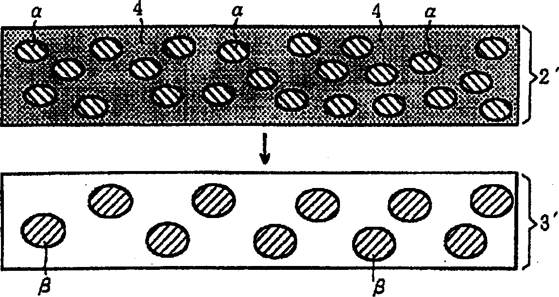
[0057] Green sheet (2') of low temperature firing layer:

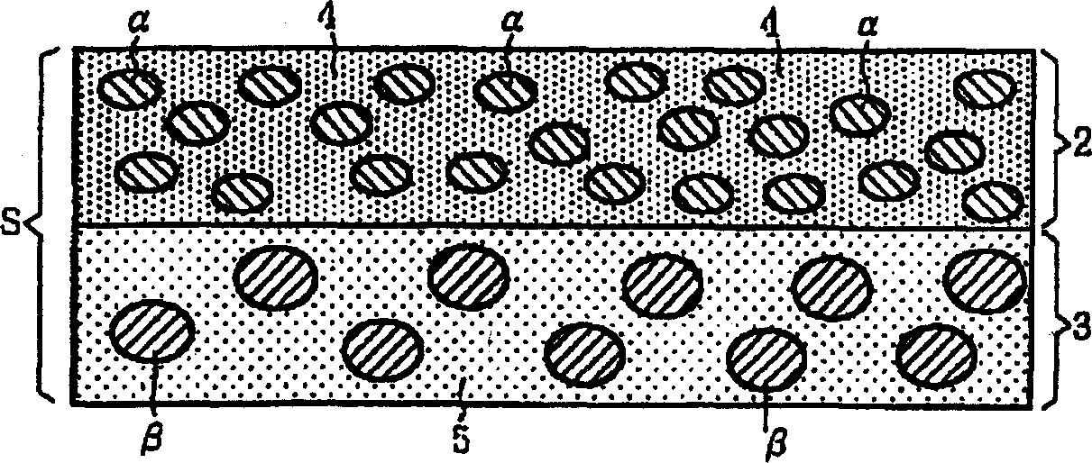
[0058] In each example (Examples 1-5 and Comparative Examples 1-3), Al with the average particle size and specific surface area shown in Table 1 was prepared. 2 o 3 (alumina) and including SiO 2 (Silicon dioxide), Al 2 o 3 (Al2O3) and B 2 o 3 (Diboron trioxide) Borosilicate glass powder (4) as the main component is used as ceramic particles α and glass powder, respectively. In addition, an acrylic adhesive and DOP (dioctyl phthalate) are prepared as an adhesive component and a plasticizer component, respectively, when forming a low-temperature firing layer green sheet (2').

[0059] Mix ceramic particles α(Al 2 o 3 Al2O3) and glass powder (4) (in Table 1, the upper row indicates weight percent, and the lower row indicates volume percent), and 12 parts by weight are packed into a jar, on the basis of 100 ...


PUM

PropertyMeasurementUnit
shrinkage factoraaaaaaaaaa

Abstract

A wiring board including a laminate comprising: a low-temperature fired layer (2) comprising ceramic particles ± and a glass component (4); and a ceramic layer (3) comprising ceramic particles ² that do not sinter at the firing temperature of the low temperature fired layer (2) and a glass component (5), wherein the ceramic particles ² have a mean particle size larger than that of the ceramic particles ± and a specific surface area smaller than that of the ceramic particles ±.

Description

technical field [0001] The present invention relates to a wiring board having less sintering shrinkage in the planar direction and a manufacturing method for producing such a wiring board. Background technique [0002] In recent years, low-temperature firing boards capable of simultaneous sintering with low-resistance conductors such as silver (Ag), gold (Au), copper (Cu), and palladium (Pd) have been used in wiring boards used in fields such as mobile communications. . Also, in the field of mobile communications, while individual electronic components are being miniaturized, the development of modular components integrating these components has progressed. As a board used in such a module part, a module board on which a low-temperature fired board is widely used, individual electronic parts and the like are mounted on the surface of the board with solder. In the mounting step, solder paste printing or component mounting is performed. Generally speaking, the installation ...

Claims


Application Information

Patent Timeline
Patent Type & Authority Applications(China)
IPC IPC(8): H05K1/03H01L23/15H01L23/498H05K3/46
CPCH01L2924/0002H01L2924/09701H05K2201/0209H01L23/49822H05K3/4688H05K1/0306H01L23/15H05K3/4629Y10T428/24917Y10T428/24926Y10T428/252
Inventor 多贺茂高桥裕之
Owner NGK SPARK PLUG CO LTD
Why Eureka
Try Eureka