Green welding laser

A laser and beam technology, applied in lasers, laser welding equipment, laser components, etc., can solve problems such as excessive peak energy application, inconsistent welding structure, evaporation of metal and alloy components, etc.

Active Publication Date: 2004-08-04
UNITEK MIYACHI +1
View PDF0 Cites 5 Cited by
  • Summary
  • Abstract
  • Description
  • Claims
  • Application Information

AI Technical Summary

Problems solved by technology

However, using a high-energy pulse can lead to considerably lower efficiency before the melting temperature is reached, so that the effective part of the laser beam is not absorbed at the beginning of the pulse
In addition, once the laser pulse is coupled to the material, the very high peak energy may be applied too much, causing material splashing (radiation droplets that melt the metal) or causing unwanted evaporation of metal and alloy components
This undesired inefficiency and splatter can create inconsistent weld structures

Method used


Image

  • Green welding laser
  • Green welding laser
  • Green welding laser

Examples


Embodiment Construction

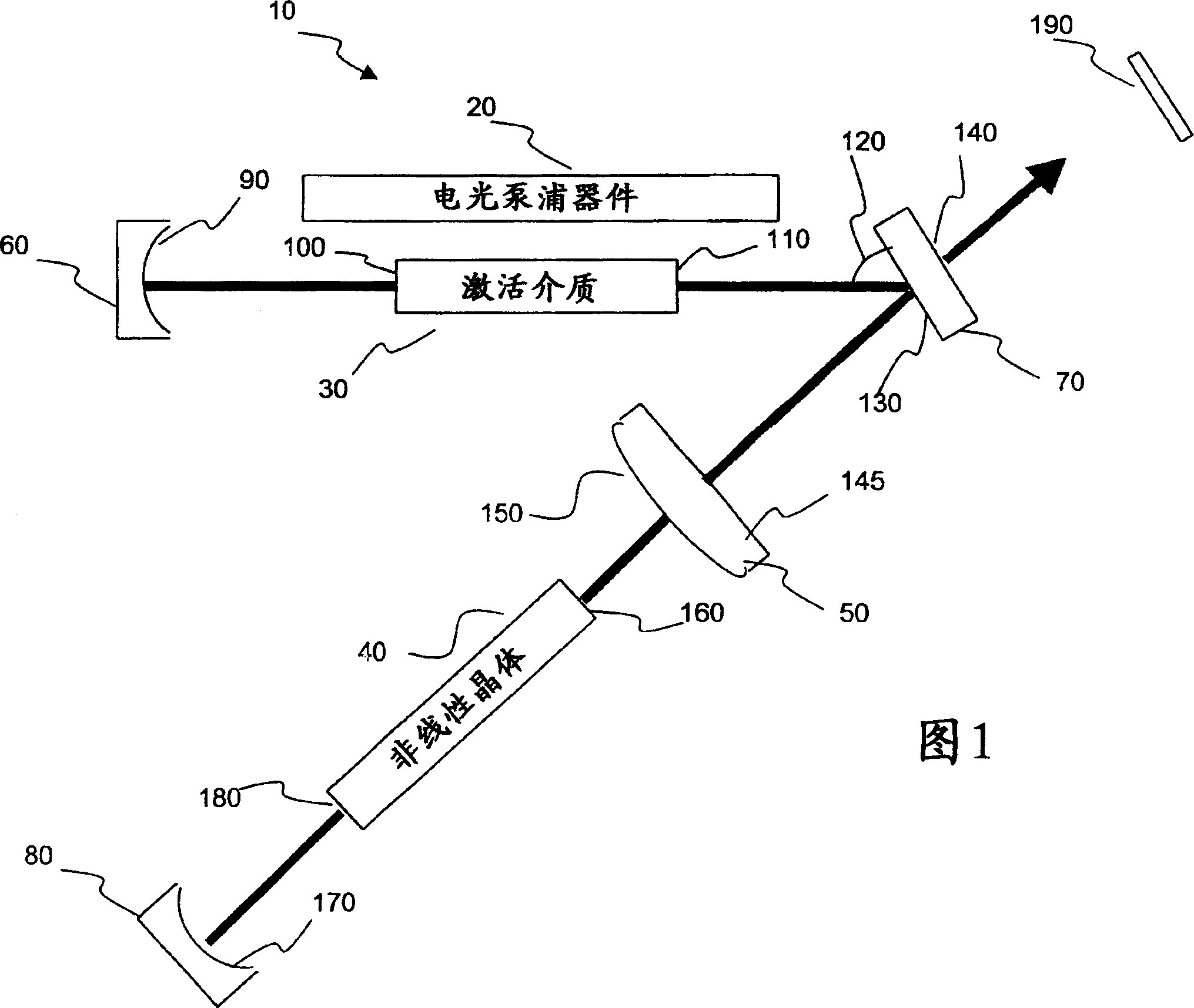
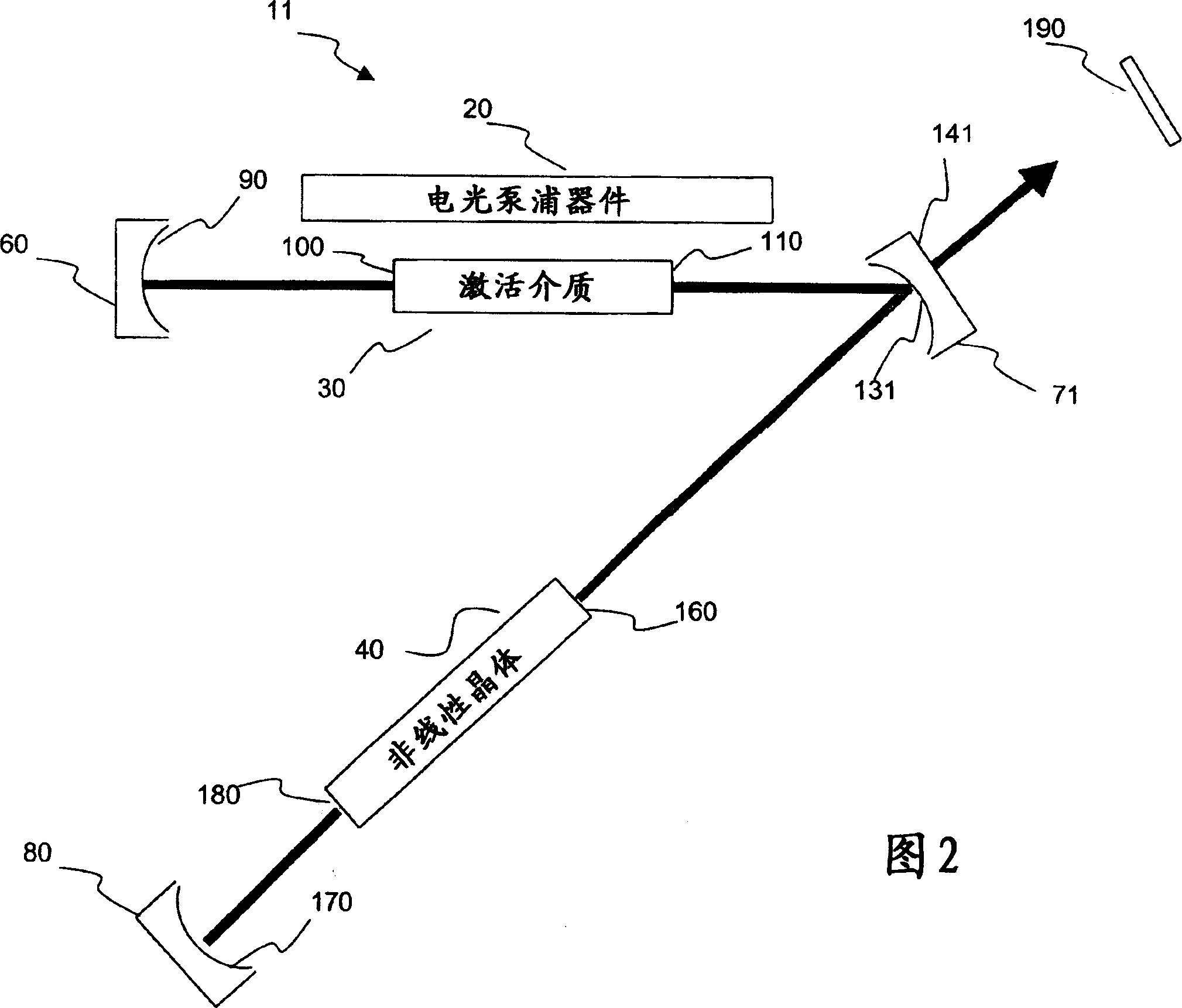
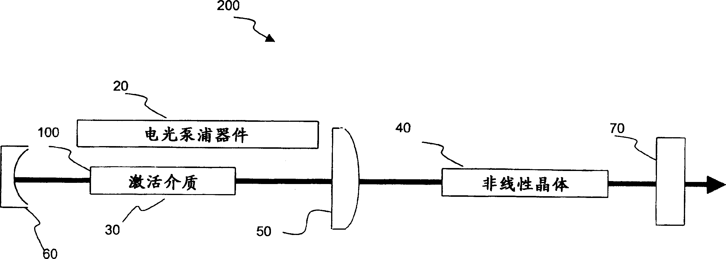
[0011] One embodiment of the present invention provides a method and apparatus for generating an Nth harmonic frequency beam (N≧2). According to one embodiment, the harmonic optical resonator comprises an electro-optic pump device (e.g., laser diode, flash lamp, etc.) that generates output pump radiation that is optically coupled into an active medium disposed within the optical resonator to pump This active medium is pumped and the optical cavity is excited at the fundamental wavelength. In the above embodiments, the nonlinear electro-optic medium can be coupled with the excited fundamental optical mode of the optical resonator to generate harmonic photons. The advantages of the present invention are best understood in the application shown below, for example, in a laser welding system.

[0012] FIG. 1 is a simplified schematic diagram showing an exemplary optical cavity for generating a beam to weld a workpiece 190 . The beam can be pulsed or continuous wave. The describe...


PUM

PropertyMeasurementUnit
conversion efficiencyaaaaaaaaaa

Abstract

A harmonic system for use with metals and alloys such as titanium, steel, copper, gold, aluminum, etc. is disclosed. The harmonic laser system includes an oscillator cavity having a first end mirror and a harmonic separator mirror, an active medium positioned in the oscillator cavity, an electro-optic pump device for optically pumping the active medium to produce a first optical beam at a fundamental wavelength and a nonlinear optical crystal positioned in the oscillator cavity to generate a second optical beam at a harmonic wavelength of the first optical beam, wherein the harmonic separator mirror outputs the second optical beam and reflects the first optical beam.

Description

technical field [0001] This invention relates generally to optical harmonic generators, and more particularly to optical harmonic generators for use in laser spot or weld seam systems to generate an output laser beam. Background technique [0002] Recently, lasers have been used in industrial production, especially for welding, cutting, and surface treatment. In practice, laser welding technology is becoming more and more important, mainly due to its high precision, high processing rate, low thermal stress on the workpiece and the degree of automation it can achieve. Current laser welding systems typically use carbon dioxide (CO 2 ) laser that produces a beam with a wavelength of 10.6 μm (micrometers), or a solid-state device like an Nd:YAG laser (neodymium yttrium aluminum garnet) that produces a beam with a wavelength of about 1.064 μm . [0003] However, light from CO2 lasers may not couple to or be absorbed efficiently by certain metals and alloys. For example, the h...

Claims


Application Information

Patent Timeline
Patent Type & Authority Applications(China)
IPC IPC(8): G02F1/37B23K26/00H01S3/08H01S3/081H01S3/109
CPCH01S3/0815H01S3/109H04M1/82
Inventor 中山伸一格瑞士·凯尔卡格莱格瑞·贝茨
Owner UNITEK MIYACHI
Why Eureka
Try Eureka